

Inside spaceflight / 03Inside the engine
Merlin: inside Falcon 9’s rocket engine
Behind the bright exhaust are three linked problems: feed the fire, keep it stable and save the wall. Merlin’s pumps, injector and cooling passages solve them together.
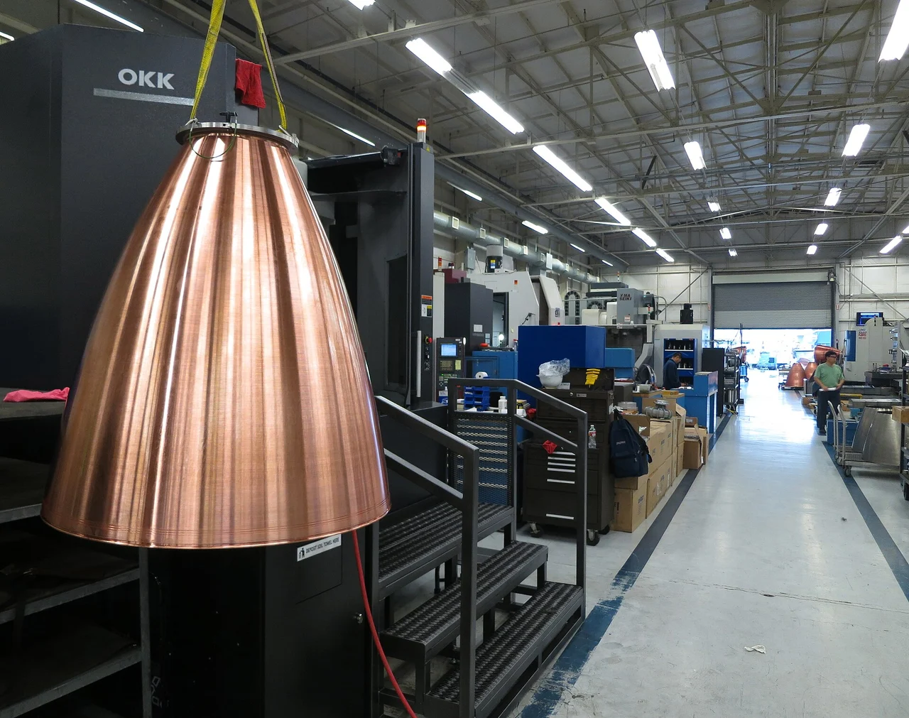
Start with the copper wall
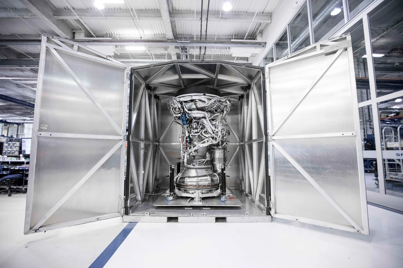
Before a Merlin becomes a bright plume, it is a piece of manufactured hardware. The copper-colored nozzle in the opening photograph makes one of its hardest jobs tangible: heat must cross a metal wall quickly enough for the wall to survive. SpaceX describes a milled copper-alloy liner in the regeneratively cooled thrust chamber and nozzle. [1]
That thermal problem is tied to two others. Propellant must enter against chamber pressure, and it must burn steadily after passing through the injector. The engine’s familiar bell is the downstream end of a system of liquid passages, rotating machinery and carefully controlled combustion. [1] [2]
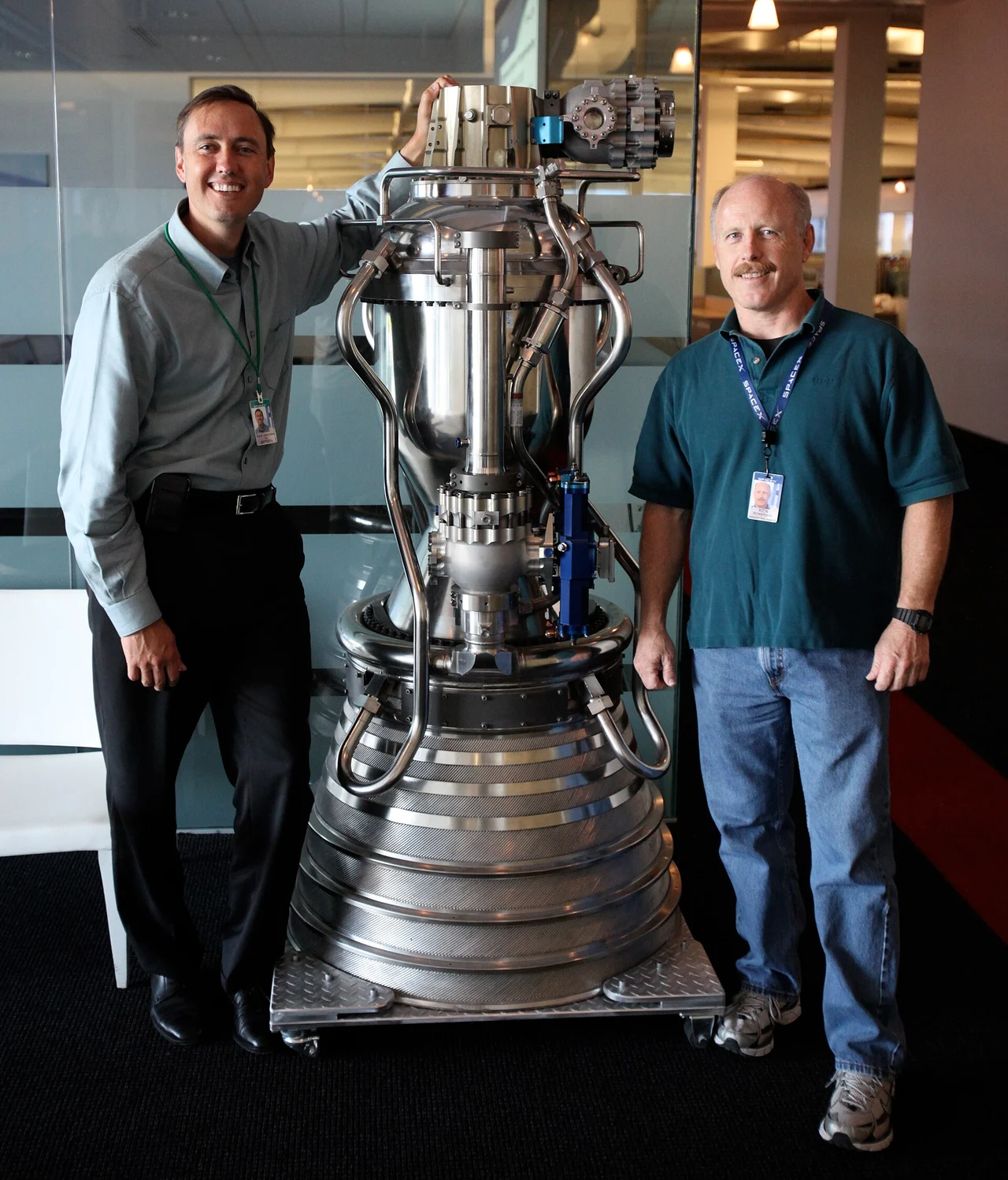
The Merlin family handles several roles. SpaceX’s May 2025 guide identifies nine M1D engines on Falcon 9’s first stage and one MVac above it. The older Merlin 1C below is useful for seeing a complete engine beside people; its August 2010 date and version belong with the photograph. [1]
The injector gives the fire a place to live
Merlin burns liquid oxygen with RP-1, a rocket-grade kerosene. The oxygen is carried aboard, so combustion can continue without atmospheric air entering the chamber. The propellants start in separate tanks and reach the engine through separate feed paths. Their eventual meeting at the injector is the beginning of the combustion process, not the beginning of the supply system. [3] [2]
SpaceX identifies a pintle injector and credits it with combustion stability. The injector organizes propellant entry into the chamber. Stability matters because the goal is sustained energy release without destructive pressure oscillations. The public guide establishes the injector type, while leaving its detailed geometry outside the scope of this explanation. [1] [4]
Inside a liquid rocket engine
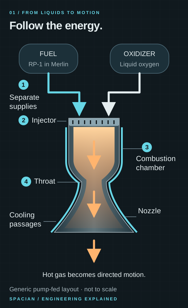
- Fuel and oxidizer arrive through separate feed paths; this drawing begins after the feed machinery.
- The injector brings the streams into the chamber. Combustion heats and pressurizes the gas.
- The throat sets the choked flow; the widening nozzle accelerates the supersonic exhaust.
Original Spacian illustration · [2] [5] [1] Download diagram ↗
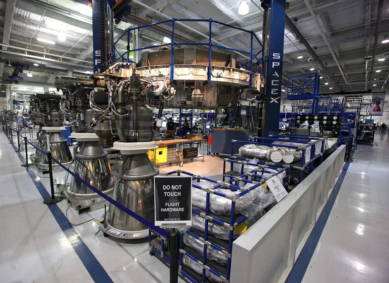
Upstream, the oxygen and fuel pumps raise the liquid pressure enough to supply that injector. Downstream, the chamber and nozzle turn the reacting flow into exhaust. The cutaway separates these functions; the factory photograph shows how much surrounding hardware a finished engine needs. [1] [2]
A single shaft links two pumps and a turbine
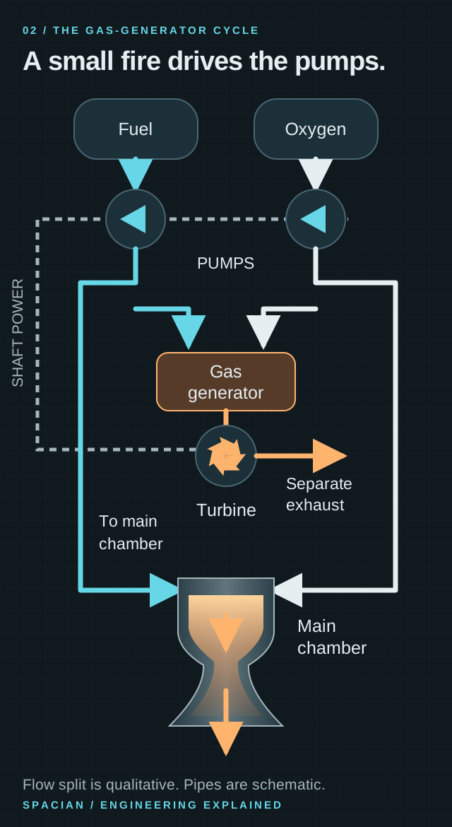
A smaller propellant flow burns in the gas generator. Its hot gas drives a turbine, and the turbine powers the propellant pumps through a shaft. SpaceX specifies a single shaft shared by the liquid-oxygen pump, fuel pump and turbine. That mechanical link is the part to look for in the diagram: chemical energy becomes rotation, then increased liquid pressure. [1]
The shaft connects rotation, not the two liquids. Fuel and oxygen stay in separate feed paths. A smaller propellant stream burns in a gas generator to drive the turbine, while most propellant goes to the main chamber. The turbine exhaust follows an open-cycle route instead of returning to that chamber. [1] [6]
This arrangement couples the engine’s demands. Pump pressure, flow, turbine power and rotating speed must agree at an operating point. Changing the thrust setting means moving a whole linked system to another workable condition. The shared shaft is a compact mechanical connection inside a much larger balance. [7] [1]
Follow the pump-power loop
Follow the colored liquid and hot-gas paths; the dashed line carries shaft power.
Generic gas-generator-cycle schematic. It explains the flow paths, not Merlin’s exact plumbing, dimensions, mixture ratios or operating pressures.
- The main propellant supply feeds the thrust chamber. The branch to the gas generator powers the feed machinery.
- A turbine converts hot-gas energy into rotation. The dashed line shows a mechanical shaft, not another fluid pipe.
- In this open cycle, turbine exhaust does not enter the main high-pressure chamber. Exact discharge routing varies by engine.
Original Spacian illustration · [6] [8] [1] Download diagram ↗
Go deeper: why one shaft is a design choice
A pump’s useful output depends on both pressure rise and volume flow. Different propellant densities can therefore create different pump requirements for a given mass flow. NASA’s turbopump monograph explains why propellant pairs with similar densities can suit a common shaft, while oxygen/hydrogen engines may use different shaft speeds or gearing. That general design logic helps explain the significance of Merlin’s documented shared shaft. [7]
The copper wall does two jobs at once
SpaceX describes a regeneratively cooled thrust chamber and nozzle with a milled copper-alloy liner. Copper alloy is part of the heat-transfer solution: the wall must move heat out of the hot-gas side while carrying substantial pressure differences. Propellant flowing in adjacent passages takes that heat away before continuing through the engine. [1] [9]
The cross-section below separates the roles. Hot combustion gas heats the inner liner. Heat crosses the metal into flowing coolant; an outer structure closes and contains the passages. The coolant and combustion gas do not mix across an intact wall. NASA’s channel-manufacturing reference discusses closing out those channels while containing high-pressure coolant—a manufacturing problem as well as a thermal one. [9]
Cooling does not require the metal to reach the gas temperature. Heat flows across a temperature gradient: from hot gas to the liner, across the liner and into the moving coolant. Reducing thermal resistance helps heat escape, but the wall must also carry pressure and survive repeated thermal loading. This is why material, channel geometry and structure are designed together. [9] [10]
How a wall survives beside the fire
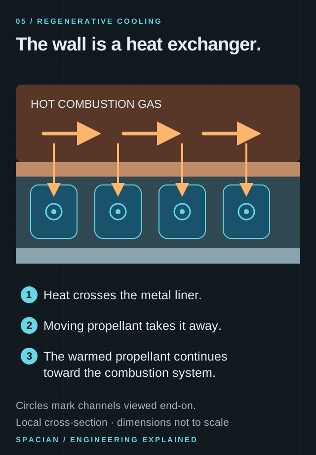
- Heat flows through the wall into the coolant. The coolant does not mix with the hot gas inside an intact wall.
- The circles depict fluid flowing into or out of the page, not sealed cavities. Actual channel geometry varies.
- SpaceX identifies regenerative cooling and a milled copper-alloy liner in Merlin’s thrust chamber and nozzle.
Original Spacian illustration · [1] [9] Download diagram ↗
Go deeper: a hot gas and a cooler wall can coexist
In steady operation, the heat arriving at a small wall region must be carried away. A thinner conductive path can reduce the temperature drop across the metal, while increased coolant flow can carry away more energy. Neither change is free: thickness affects strength, and coolant passages impose pressure losses. The manufacturing problem is to create and seal those passages while retaining the chamber’s required structural performance. [9]
The upper stage gives Merlin more room to expand
The upper-stage Merlin Vacuum has a larger expansion nozzle because it works in much lower ambient pressure. SpaceX’s May 2025 guide describes its fixed nozzle with an exit-to-throat area ratio of 165:1. That is an area ratio: for circular sections the corresponding diameter ratio is about 12.8, not 165. [1]
The same guide gives up to 845 kilonewtons per first-stage M1D at sea level and 981 kilonewtons for the upper-stage MVac in vacuum. These are documented values with different operating conditions. The numerical difference cannot be assigned to nozzle geometry alone. Ambient pressure itself affects thrust, and the complete engine configurations are not identical. [1] [11]
The conditions explain the hardware. At liftoff, the compact nozzle must operate with substantial pressure outside. The upper-stage nozzle works in far lower pressure, so it can expand the gas through a much larger area ratio. The 845 kN and 981 kN figures below retain their different sea-level and vacuum labels; they are not a controlled experiment isolating nozzle geometry. [1] [11]
165 to one is an area ratio
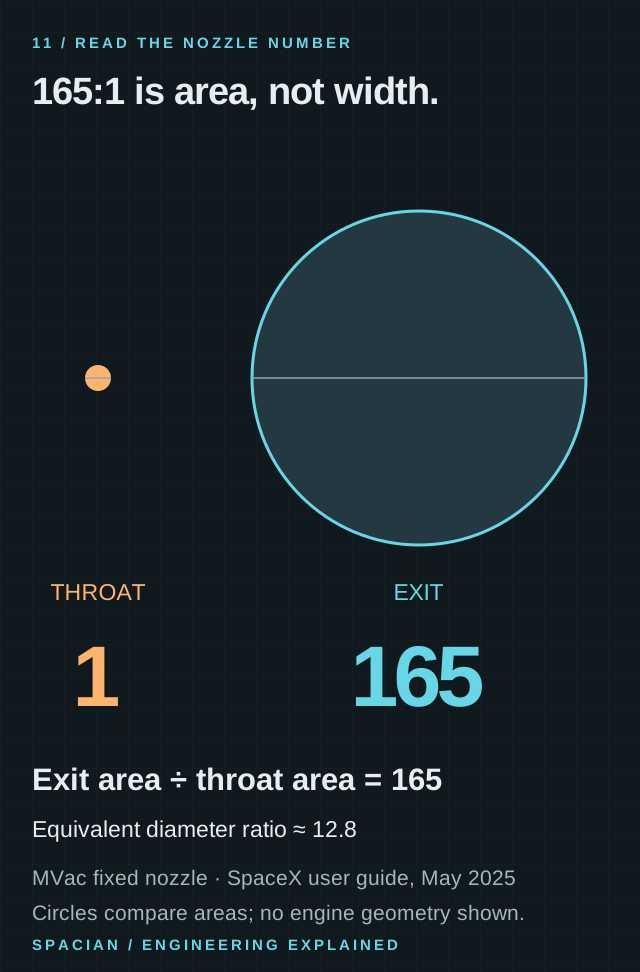
- Expansion ratio compares nozzle exit area Aₑ with throat area Aₜ. It does not compare their diameters.
- For circular sections, a 165:1 area ratio means a diameter ratio of √165, approximately 12.8.
- SpaceX’s May 2025 guide lists 165:1 for its fixed MVac nozzle. This is a dated documented configuration, not a measurement of every photograph.
Original Spacian illustration · [1] Download diagram ↗
The second ignition is a design requirement
A mission with a coast followed by another burn needs more than an engine that can run steadily. It needs another reliable start. SpaceX documents redundant TEA-TEB pyrophoric igniters on MVac: an ignition fluid system whose chemistry initiates combustion. The stage also has to point correctly and supply propellant for the new burn. [1]
Reflying hardware adds the ground interval to that story. SpaceX documents acceptance testing and Merlin refurbishment at McGregor. Inspection and preparation sit between the previous shutdown and the next ignition. The useful unit of understanding is the whole engine over its operating cycle, not a bell seen during one bright second of a webcast. [1]
The result is a useful change in how the engine looks. The factory copper wall is a heat-transfer path. The crowded hardware above it is a supply and power system. The wide upper-stage bell is an expansion device. Together they make the sequence from ignition to shutdown—and, when required, ignition again—possible. [1] [9]
Read the evidence
Sources & image credits
- SpaceX · Falcon User’s Guide, May 2025 ↗
- NASA Glenn · Liquid rocket engine ↗
- SpaceX · Falcon 9 and Merlin ↗
- NASA · Solving combustion instability in the F-1, 2019 ↗
- NASA Glenn · Nozzle design ↗
- NASA NTRS / AIAA · Liquid propulsion systems, engine power cycles ↗
- NASA SP-8107 · Turbopump Systems for Liquid Rocket Engines, 1974 ↗
- NASA · Saturn V, starting the F-1 engine, Appendix B ↗
- NASA Technology Transfer · Coolant channels in rocket chambers and nozzles ↗
- NASA Glenn · Historical nozzle-cooling research ↗
- NASA Glenn · Rocket thrust equation ↗
Technical explanation by Spacian, reviewed against the linked sources. Photographs retain their original dates, creators and reuse terms in their captions. Original diagrams explain mechanisms and do not reproduce engineering drawings or flight telemetry. Editorial policy and corrections.
Continue the story
Follow the mechanism
 Rocket anatomy
One rocket. Two different flights.
Explore Falcon 9’s Merlin engines, two stages, payloads and booster recovery, with photographs and diagrams that explain how the flight fits together.
Read the explanation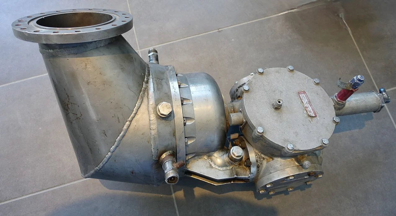 Engine mechanisms
The engine inside the engine.
Trace fuel, oxidizer, turbine and pumps through a gas-generator rocket engine, and understand the open-cycle tradeoff behind engines such as Merlin and F-1.
Read the explanationHow things workBuild the bell for space.
Discover how a rocket nozzle turns hot gas into speed, why vacuum engines use large bells and how outside pressure changes the design problem near the ground.
Read the explanation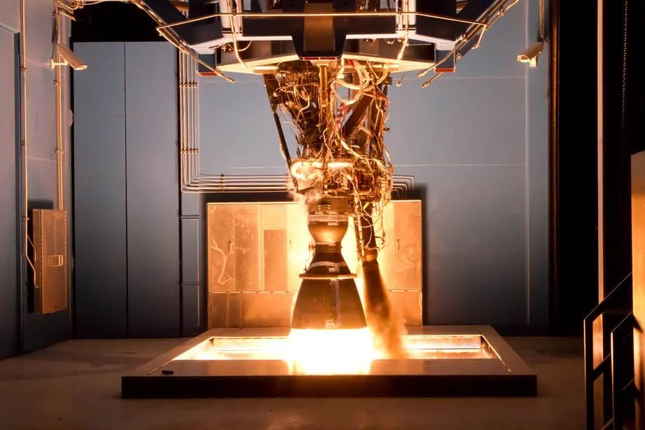 How things work
From liquid to liftoff.
Follow fuel, oxidizer and exhaust through a rocket engine, and discover why it works in empty space, how the nozzle makes thrust and what the pumps do.
Read the explanation