

Inside spaceflight / 06How things work
The fuel takes the heat before it burns
The small openings around this copper chamber are part of its survival system. Before propellant feeds the fire, it can carry heat away from the metal holding that fire in place.
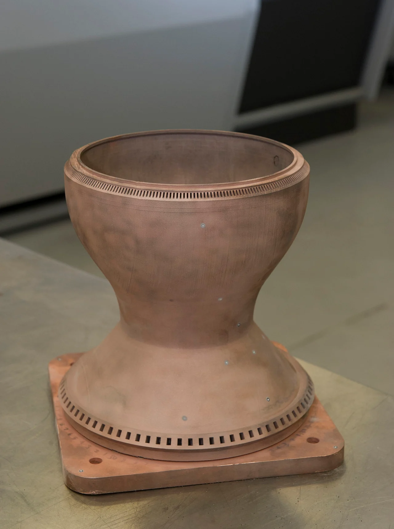
Look at the rim before looking at the flame
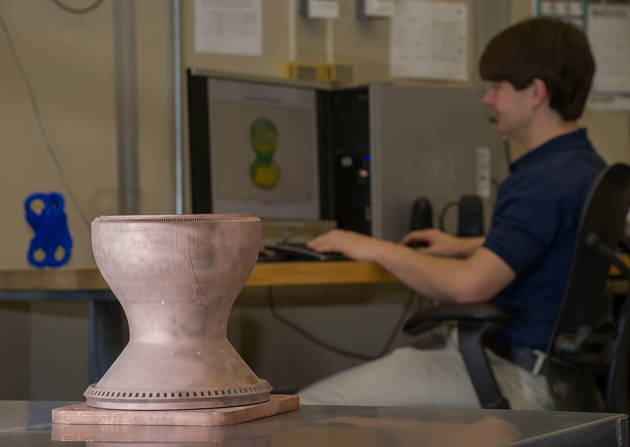
In NASA’s 2015 photograph, the chamber looks deceptively simple: a copper-colored cylinder narrows at the throat and opens into a short nozzle. Around its rim is a close-spaced row of small openings. Inside the wall, more than 200 passages were built to carry coolant. Those hidden passages matter as much as the cavity where combustion will happen. [1]
NASA’s Marshall team made the liner by fusing successive layers of copper-alloy powder. The part still needed a structural jacket and testing; a photograph of a liner is not a photograph of a complete flight engine. It does, however, make an otherwise invisible requirement tangible: an engine wall must contain hot gas while passing heat through to another flowing material. [1] [2]
This is why the flame temperature alone cannot tell you whether an engine will melt. The gas can be much hotter than the metal’s permissible operating temperature. Whether the wall survives depends on how quickly heat arrives, how it crosses the metal, and how effectively the cooling system removes it. [3]
One wall, three different temperatures
Start at a small patch of chamber wall. Hot gas transfers energy toward its inner surface. Heat then conducts through the metal to a cooling passage. Flowing coolant carries that energy downstream. In steady operation, heat does not need to accumulate in the wall: the incoming and outgoing rates can balance while a large temperature difference remains across the system. [3]
The metal’s hot face is cooler than the gas, and its coolant-side face is cooler still. The coolant next to that face also differs from the bulk fluid farther into the passage. Each step presents a resistance to heat transfer. A highly conductive liner helps with the metal step, but it cannot compensate for a poorly supplied cooling channel or a local hot spot. [3] [2]
Follow the heat across the wall
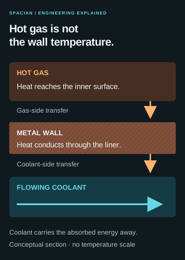
Conceptual local cross-section. The arrows show heat transfer and coolant flow, not a particular engine’s dimensions or measured temperatures.
- Conceptual local wall section, not to scale. No numerical temperature or heat-flux field is encoded.
- Gas, hot wall face, coolant wall face and bulk coolant need not share a temperature.
Original Spacian illustration · [3] [2] Download diagram ↗
Cooling therefore changes how to read a chamber cross-section. A thin inner wall shortens the conduction path, while an outer structure helps the assembly carry pressure and thrust loads. The useful solution is an integrated structure: material, passage shape, attachment and fluid supply must work together. [2]
The coolant still has a job to do
In regenerative cooling, one or both propellants circulate around the wall as coolant. In a simplified fuel-cooled route, fuel enters the passages, absorbs heat, and continues through the engine’s feed system toward combustion. The energy picked up from the wall stays in a fluid that the engine was already carrying. [3] [2]
That makes the coolant a moving heat sink. It is not a jacket of liquid left sitting beside the flame: warmed fluid must leave and be replaced by incoming flow. The complete route depends on the engine cycle. Some engines use the heated propellant elsewhere in the power system before it reaches the main chamber; the simple loop in the figure is a teaching layout, not Merlin or RS-25 plumbing. [4] [3]
Fuel visits the wall before the fire
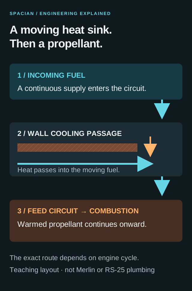
Simplified regenerative route. Real engine circuits can contain additional branches, valves, turbines and separate cooling paths.
- Simplified fuel-cooled route; real engines can include branches and power-cycle components.
- Arrow sequence expresses fluid routing, not flight timing or engine dimensions.
Original Spacian illustration · [3] [2] [4] Download diagram ↗
On the redesigned RS-25 nozzle, NASA describes more than a thousand wall tubes carrying very cold hydrogen. The construction method differs from the printed copper liner, but the thermal task is recognizable: move heat through a wall into a continuing propellant flow. The photograph below shows the March 2023 ground-test setting, not the coolant itself. [5]
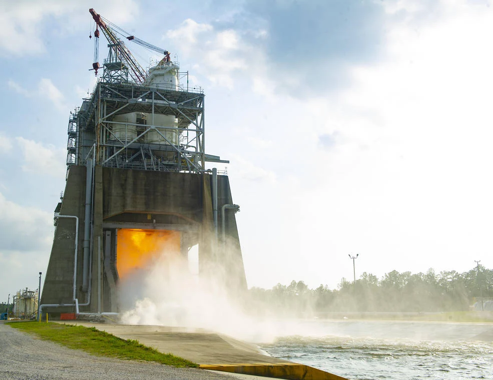
The channel is part of the machine
A channel is not simply empty space cut into the wall. Its height, width and neighboring ribs determine the available flow area, the cooled surface and the path through the metal. NASA’s channel research examined taller, narrower passages as a way to change this heat-transfer geometry. A geometry that cools effectively must also be practical to manufacture and close without blocking the passage. [6] [2]
Additive manufacturing changes which internal shapes are possible, but does not remove the need to inspect them. In the 2015 work, structured-light scanning helped compare the printed part with its intended shape. Material characterization and later hot-fire testing were separate steps. A printer finishing its last layer does not establish the chamber’s thermal margin or service life. [1] [7]
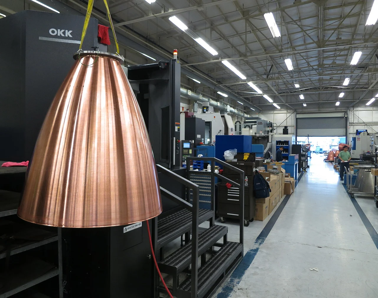
Nor is the whole engine necessarily one cooling architecture. NASA’s LLAMA project paired an additively manufactured copper-alloy chamber with different nozzle technologies, including composite nozzles. That work examined the interfaces as well as the individual parts. The chamber and its downstream extension can face different thermal and structural demands. [7]
Why a good cooling design still needs a life test
Engine starts and shutdowns heat and cool the structure repeatedly. Local temperature gradients and pressure loads act together, and changes in a joint or passage can alter local cooling. NASA’s chamber-design monograph treats thermal, structural and life considerations together. A steady heat-balance example cannot predict those accumulated effects. [3]
Sometimes protection sits on the hot side
Film cooling puts a comparatively cooler fluid layer along the gas-facing surface. Its purpose is to reduce the thermal exposure of the wall before the heat has crossed the metal. The film mixes with the main stream as it travels, so injection location, direction and distribution matter. It is a flow that must stay useful along the surface, not a permanent insulating sheet. [8]
The F-1 provides a revealing historical example. Its nozzle extension used turbine exhaust as a cooling film. Calling the coolant a hot gas is not a contradiction: it could still protect a surface from the much hotter main exhaust. NASA’s nozzle monograph describes how flow reattachment, uneven distribution and distortion could defeat that protection locally. The engineering problem was keeping the film where it was needed. [8]
Three ways to protect a wall
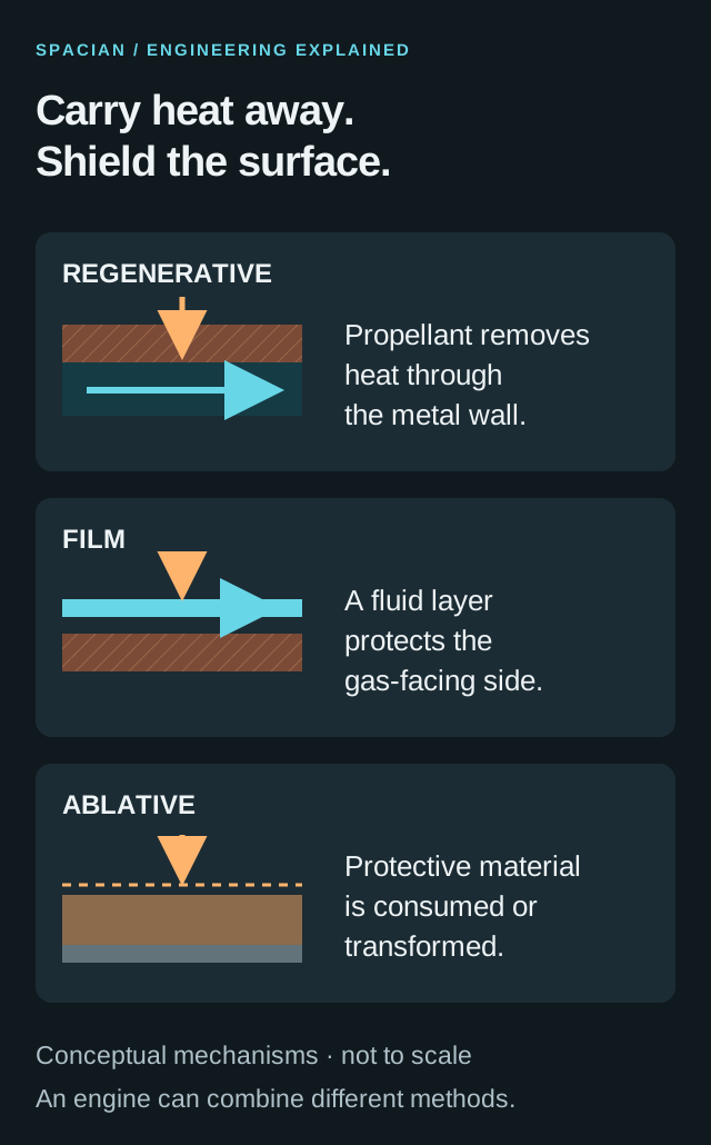
Conceptual comparison. These methods can be combined, and the drawing does not rank their suitability for every engine.
- Qualitative diagrams show different mechanisms, not ranked performance.
- Methods can coexist within the same thrust-chamber assembly.
Original Spacian illustration · [3] [8] [9] Download diagram ↗
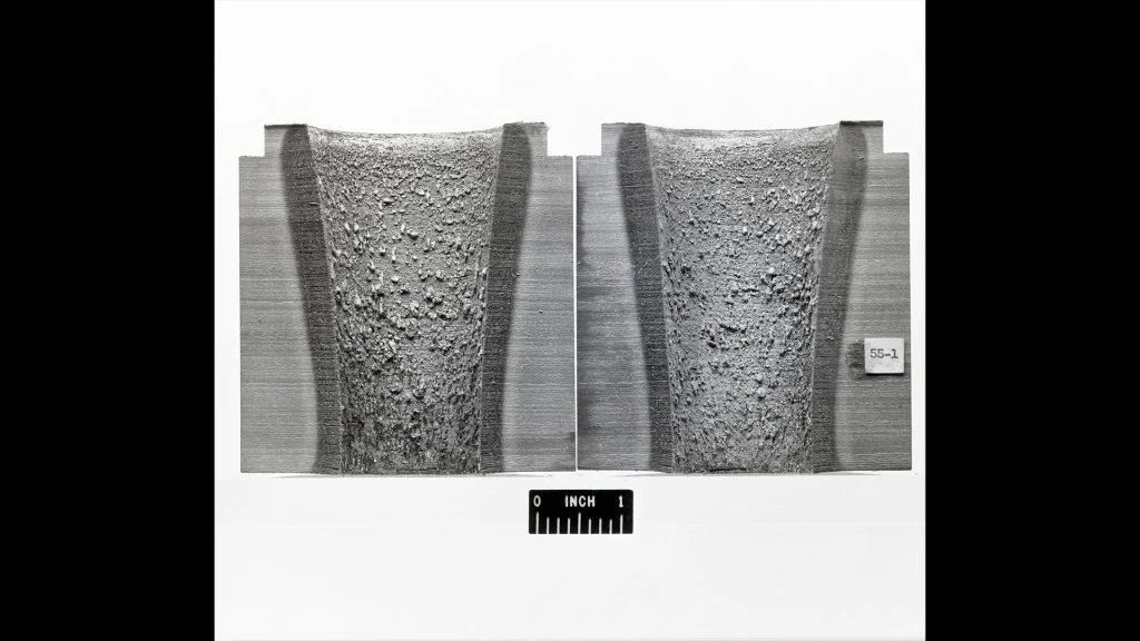
An ablative lining takes another approach. It is deliberately consumed or transformed during operation, absorbing heat and protecting material below. NASA’s Lewis researchers compared candidate nozzle and throat materials in the 1960s. The cut sections in this archive photograph expose the protective material instead of a network of coolant passages. Available thickness and allowable erosion become part of the operating budget. [9]
Two temperature rises, with different meanings
A small teaching calculation separates conduction through the metal from warming of the coolant. Choose a heat flux of 10 megawatts per square metre over a 0.02-square-metre patch: that is 200 kilowatts crossing the patch. These are selected example inputs, not measurements of a named engine. [3]
For a flat, one-millimetre wall with an assumed constant conductivity of 300 watts per metre-kelvin, the corresponding temperature drop through the metal is about 33 kelvin. If a coolant stream of 2 kilograms per second removes the same 200 kilowatts with a chosen constant specific heat of 4,000 joules per kilogram-kelvin, its bulk temperature rises by 25 kelvin. Those two differences describe different parts of the same heat path. [3]
A deliberately simplified heat balance
Chosen inputs for one steady, flat patch; no engine performance prediction. A kelvin temperature difference has the same numerical size as a Celsius degree difference.
- Heat crossing the patch
- 10,000,000 W/m² × 0.02 m²200 kW
- Temperature drop through the metal
- 10,000,000 × 0.001 / 30033.3 K
- Bulk coolant temperature rise
- 200,000 / (2 × 4,000)25 K
Neither result tells us the hot-face temperature. We have omitted the gas-side and coolant-side transfer coefficients, pressure losses, temperature-dependent material properties, boiling, chemical reactions, curvature and local hot spots. The arithmetic teaches what each term does; detailed analysis and instrumented testing establish an engine’s usable limits. [3]
A cooling system is a choice about the whole flight
Regenerative cooling asks the feed system and the wall to cooperate continuously. Film cooling asks a protective stream to remain effective where the main flow is hottest. Ablation assigns part of the heat load to material that can be sacrificed. Each answer changes the hardware, the inspection problem and the allowable operating history. [3] [8] [9]
Return to the small openings in the copper liner. They are an entrance to a larger system: incoming propellant, a manufactured heat path, a load-bearing structure and the combustion process downstream. The chamber is able to hold the fire because its design also provides a route for some of that fire’s energy to leave the wall. [1] [2]
Read the evidence
Sources & image credits
- NASA · Printed copper chamber liner, 21 April 2015 ↗
- NASA · Thrust chamber liner and fabrication method, 31 July 2024 ↗
- NASA SP-8087 · Liquid Rocket Engine Fluid-Cooled Combustion Chambers, April 1972 ↗
- NASA NTRS / AIAA · Liquid propulsion systems, engine power cycles ↗
- NASA · Redesigned RS-25 nozzle and ground test, 8 March 2023 ↗
- NASA TM-1998-206313 · Cooling-channel geometry and aspect ratios ↗
- NASA · Long Life Additive Manufacturing Assembly, 3 June 2021 ↗
- NASA SP-8120 · Liquid Rocket Engine Nozzles, pp. 34–35 ↗
- NASA Glenn history · Rocket Laboratory: low-cost ablative cooling ↗
Technical explanation by Spacian, reviewed against the linked sources. Photographs retain their original dates, creators and reuse terms in their captions. Original diagrams explain mechanisms and do not reproduce engineering drawings or flight telemetry. Editorial policy and corrections.
Continue the story
Follow the mechanism
 Inside the engine
Inside Merlin.
Inside the Merlin engine family: RP-1 and oxygen, the gas-generator cycle, cooling channels, vacuum nozzles and the different jobs engines do on Falcon 9.
Read the explanation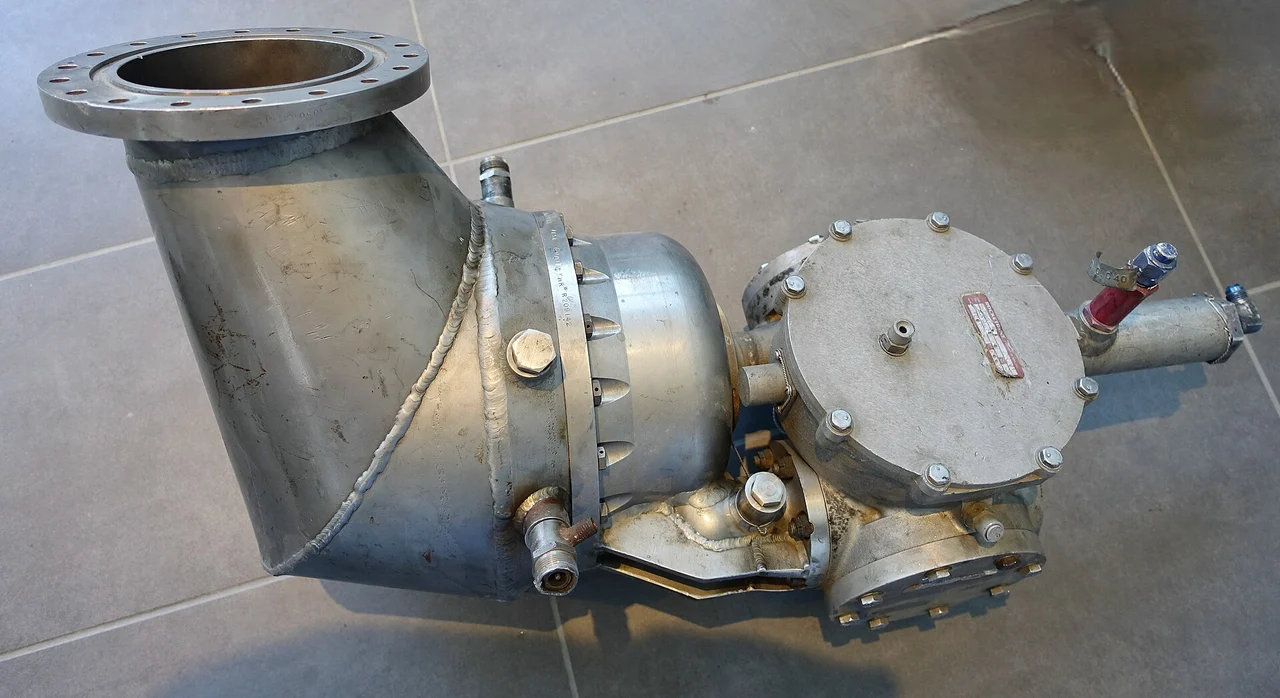 Engine mechanisms
The engine inside the engine.
Trace fuel, oxidizer, turbine and pumps through a gas-generator rocket engine, and understand the open-cycle tradeoff behind engines such as Merlin and F-1.
Read the explanation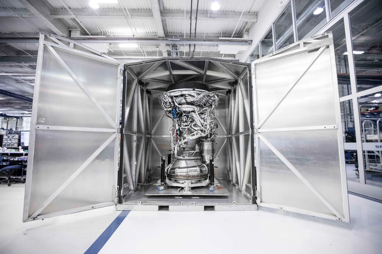 How things work
Build the bell for space.
Discover how a rocket nozzle turns hot gas into speed, why vacuum engines use large bells and how outside pressure changes the design problem near the ground.
Read the explanation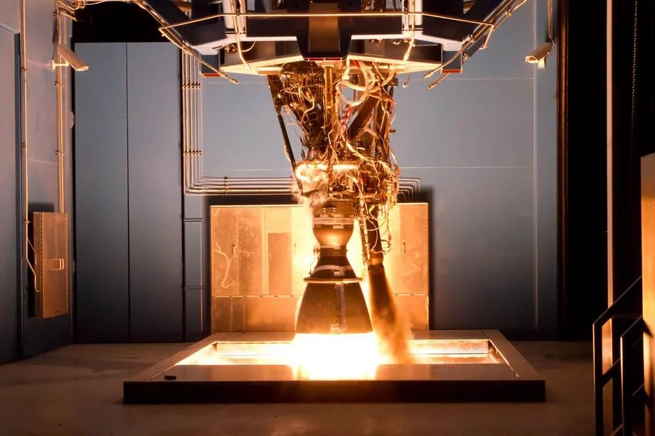 How things work
From liquid to liftoff.
Follow fuel, oxidizer and exhaust through a rocket engine, and discover why it works in empty space, how the nozzle makes thrust and what the pumps do.
Read the explanation