

Inside spaceflight / 02Engine mechanisms
The gas-generator cycle: the engine inside the engine
The pumps need power before the main chamber can make thrust. A smaller fire supplies it. Follow the energy from combustion to rotation, and see why the exhaust route matters.
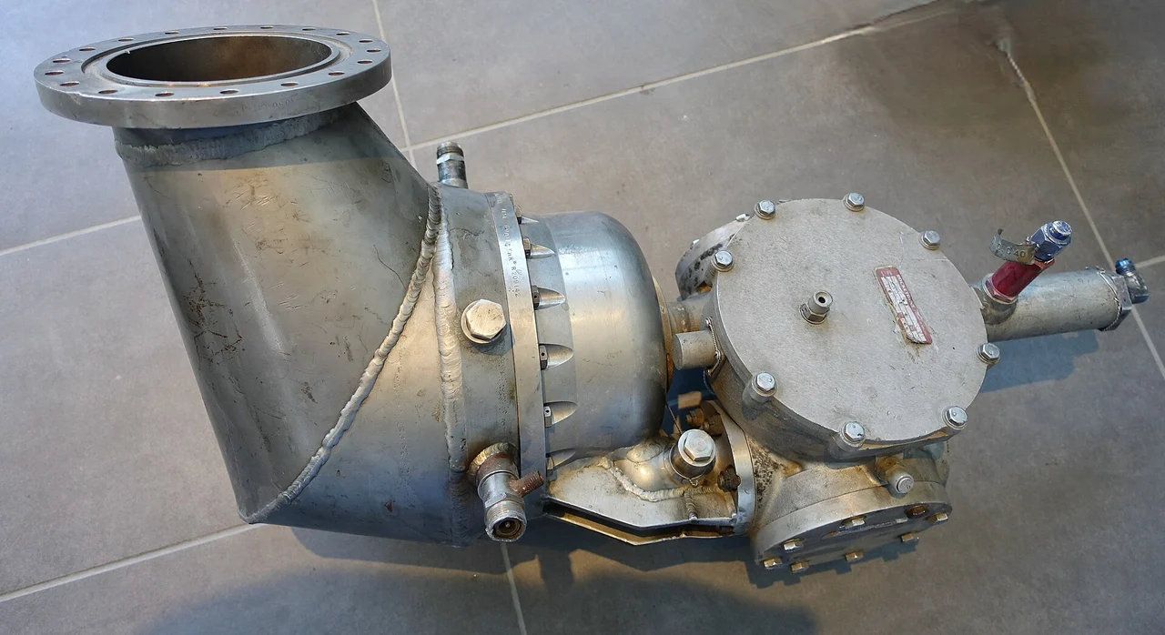
A rocket engine has to feed a fire that pushes back
The chamber is full of hot gas at high pressure. Fresh liquid cannot enter just because a valve has opened: the supply must overcome that pressure and the losses along the way. A pump-fed engine therefore contains a powerful piece of rotating machinery before the propellant ever reaches the main fire. [1] [2]
The gas generator supplies power to that machinery. It burns a smaller propellant stream, sends the resulting gas through a turbine, and uses the turbine’s shaft to drive the pumps. Chemical energy becomes rotation; rotation raises liquid pressure; that pressure keeps the main chamber supplied. [3] [4]
Two flow paths, one engine
Follow the colored liquid and hot-gas paths; the dashed line carries shaft power.
Generic functional diagram. Most propellant feeds the main chamber; a smaller flow powers a turbine and the pumps. No quantitative flow split is implied.
- The main propellant supply feeds the thrust chamber. The branch to the gas generator powers the feed machinery.
- A turbine converts hot-gas energy into rotation. The dashed line shows a mechanical shaft, not another fluid pipe.
- In this open cycle, turbine exhaust does not enter the main high-pressure chamber. Exact discharge routing varies by engine.
Original Spacian illustration · [3] [4] [5] Download diagram ↗
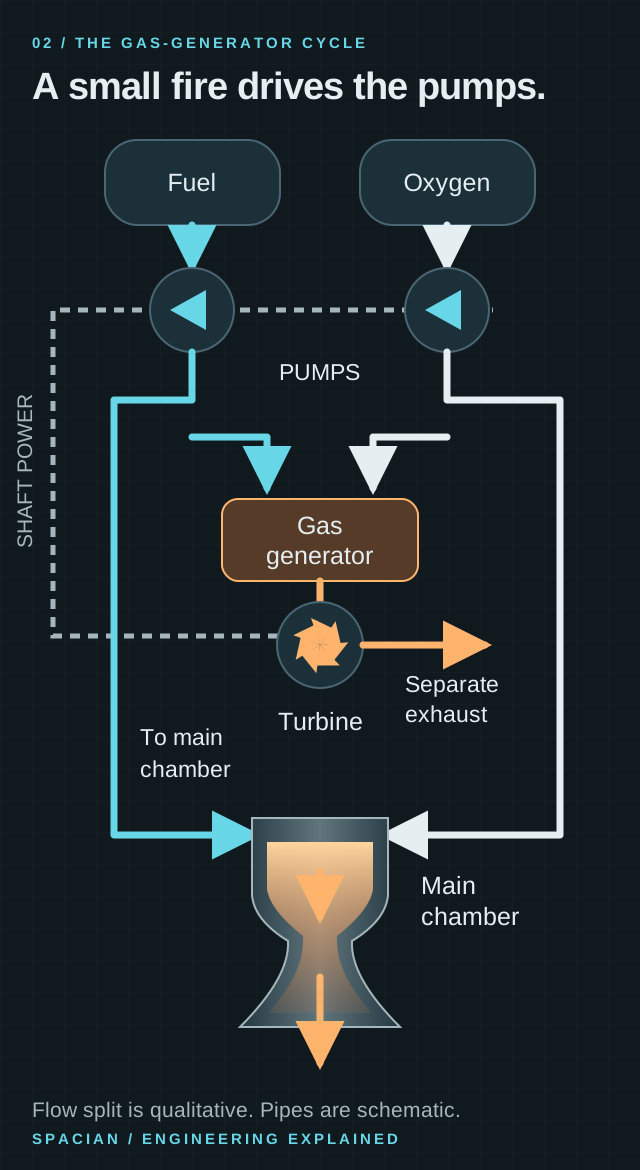
Keep three things separate as you trace the diagram: liquid moves through pipes, hot gas moves through the turbine, and the shaft transmits mechanical power. The dashed shaft is the connection that closes the power loop without mixing the liquid feed paths. [4] [5]
Put a power bill on the pump
Pressure alone does not tell you how much power a pump needs. Moving a larger volume each second against the same pressure rise costs more power. For a steady, approximately incompressible liquid, hydraulic power is volume flow multiplied by pressure rise. Shaft power is larger because a real pump has losses. [6]
Take a hypothetical liquid flow of 50 kg/s at a density of 800 kg/m³. That is 0.0625 m³ each second. Raising its pressure by 10 MPa transfers 625 kW to the liquid. With an assumed 75% pump efficiency, shaft input is about 833 kW. These chosen numbers illustrate the power balance; they are not Merlin measurements. [6]
Where 833 kilowatts goes
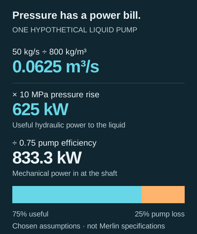
Calculated teaching example for one hypothetical liquid pump. The two output areas show the 75% useful hydraulic power and 25% pump loss shares of shaft input.
- Mass flow divided by density gives volume flow: 0.0625 m³/s.
- Volume flow × pressure rise gives 625 kW of hydraulic power.
- At 75% efficiency, shaft input is 833.3 kW; the remainder is pump loss.
Original Spacian illustration · [6] [1] Download diagram ↗
The turbine has to supply the combined demand of the pumps and any auxiliary loads. NASA’s turbopump design monograph treats this balance explicitly. It explains why the small combustor and rotating assembly are central to the engine, even though the main chamber dominates the exhaust photograph. [1]
The F-1 gave turbine exhaust a second job
After the turbine, the gas has given up some of its energy to the shaft. In a gas-generator cycle it does not return to the main high-pressure chamber. That is what makes the cycle open. The exhaust can still be routed somewhere useful. [3]
The F-1 provides a more interesting real example. NASA’s nozzle-design monograph describes turbine exhaust being distributed along the nozzle extension wall. The gas flowed through slots formed by overlapping shingles and protected that extension from the hotter main combustion stream. It was a way to dispose of turbine exhaust and help solve a cooling problem at the same time. [7]
The route kept F-1 an open-cycle engine: the turbine stream joined the nozzle’s lower-pressure expansion region. It helped protect the extension without being forced back into the main chamber. The distinction is physical—where the flow goes and at what pressure—not whether every bit of exhaust leaves through a visibly separate pipe. [7] [3]
F-1: useful work after the turbine
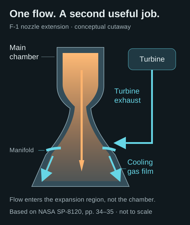
Conceptual route through the nozzle extension, based on NASA SP-8120. It is not a complete F-1 plumbing diagram.
- After driving the turbine, the gas goes to a manifold at the nozzle extension.
- Slots along the extension distribute a protective film between the hotter main flow and the wall.
- The flow enters the expansion region. It does not reenter the main high-pressure chamber.
Original Spacian illustration · [7] Download diagram ↗
Closing the cycle raises the pressure problem
The turbine stream has consumed propellant but has not followed the main chamber’s high-pressure expansion path. That is an efficiency cost. Sending turbine-driving flow into the main chamber can recover a different share of its propulsive potential, but requires an architecture that can deliver that flow into the chamber at the necessary conditions. [3]
The trade is not settled by a single efficiency ranking. Designers also have to meet mass, pressure, thermal, startup and operating requirements. NASA’s power-cycle reference discusses robust operation and lower operating-pressure demands among the gas-generator arrangement’s useful characteristics. Those can be valuable even when another cycle offers a higher theoretical performance potential. [3]
The gas-generator route gives the turbine a discharge path outside the main chamber. In staged combustion, turbine-driving flow has to remain at conditions that allow it to enter that chamber. That requirement changes the pressure balance upstream, alongside the thermal, mechanical and startup requirements of the complete engine. [3] [1]
What makes an engine cycle open or closed
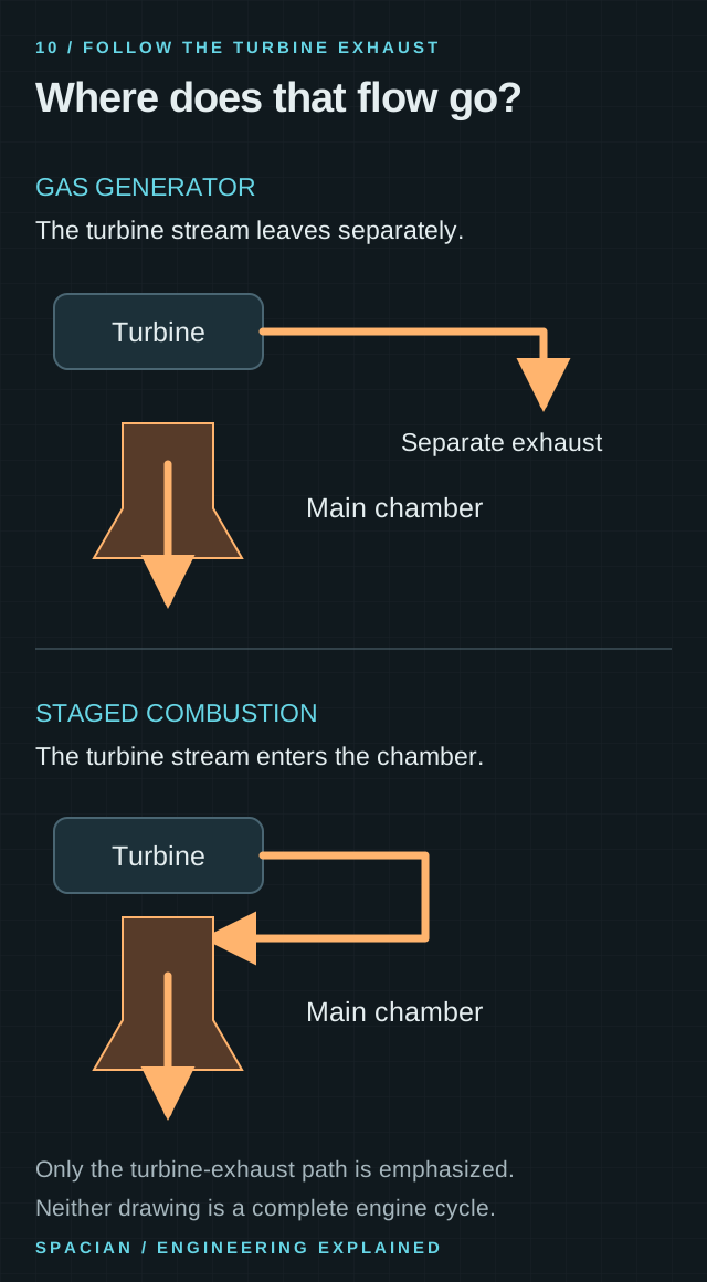
- The distinguishing route is the turbine exhaust. In a gas-generator cycle it bypasses the main high-pressure chamber.
- In staged combustion, the turbine-driving flow joins the main chamber. The complete feed architectures have additional differences.
- This comparison does not rank whole engines or assign performance figures to either design.
Original Spacian illustration · [3] Download diagram ↗
Go deeper: why the two pressures cannot be chosen independently
A turbine extracts power as gas expands through it. If its outlet must feed a high-pressure main chamber, the upstream system has to provide the pressure needed for both turbine expansion and downstream entry. A separate exhaust route changes that constraint. The final design still has to match pump demand with turbine output over starts, throttling and shutdown—not only at one steady operating point. [1]
How do you start a machine that powers itself?
At steady operation, pump output feeds the gas generator and the gas generator powers the pump. At rest, that loop has no established rotation or combustion. Startup needs an outside initiating process that brings the parts into operation in a controlled order. [4]
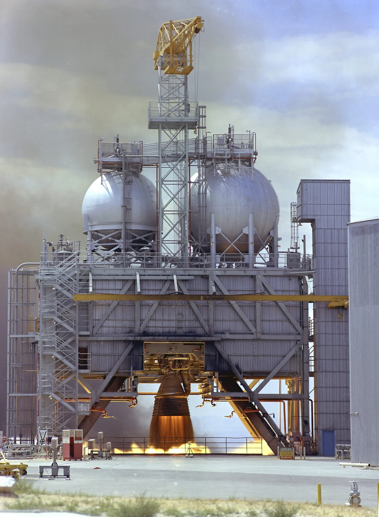
The historical F-1 sequence shows how concrete that problem becomes. Ground hydraulic pressure opened the main liquid-oxygen valves and allowed the gas-generator feed sequence to proceed. Initial combustion drove the turbine, pump pressure rose, and a hypergolic starting fluid initiated the main chamber’s combustion. As chamber pressure built, the main fuel supply opened and the engine moved toward full operation. [8]
The important insight is the sequence of causes: establish an initial supply, start the turbine drive, build pump pressure, establish chamber ignition, then admit the main flow. Different engines implement different starts. Merlin’s restart capability belongs to its own engine and stage design, rather than following automatically from the words “gas generator.” [8] [5]
Follow the energy all the way around
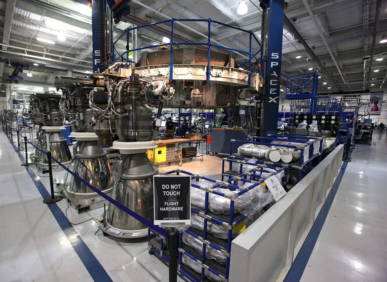
SpaceX identifies Merlin as a liquid-oxygen/RP-1 gas-generator engine and describes the shared shaft connecting its turbine and two pumps. Those details give the drawing a concrete anchor. The turbine’s job is not to generate the main thrust directly. It powers machinery that keeps the much larger combustion process supplied. [5] [9]
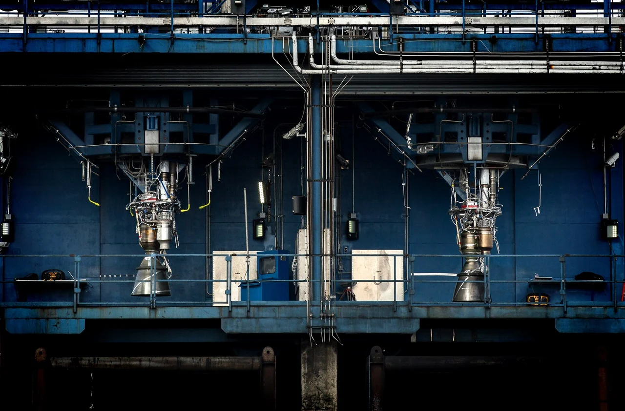
In Merlin, the oxygen pump, fuel pump and turbine share a shaft. The factory image puts physical hardware beside that statement. The rotating assembly has to satisfy both liquid circuits while the turbine draws its power from another reacting flow. It is an engine within the engine in the practical sense: a combustion-driven power plant for the feed system. [5] [1]
Trace one complete chain: a small flow burns, the turbine turns, the pumps raise pressure, the main chamber stays supplied, and the nozzle accelerates most of the exhaust. Then follow the turbine stream to its outlet. Those two journeys explain both what the gas generator contributes and what defines the cycle. [3]
Read the evidence
Sources & image credits
- NASA SP-8107 · Turbopump Systems for Liquid Rocket Engines, 1974 ↗
- NASA Glenn · Liquid rocket engine ↗
- NASA NTRS / AIAA · Liquid propulsion systems, engine power cycles ↗
- NASA · Saturn V, starting the F-1 engine, Appendix B ↗
- SpaceX · Falcon User’s Guide, May 2025 ↗
- U.S. Department of Energy · Improving Pumping System Performance, 2006 ↗
- NASA SP-8120 · Liquid Rocket Engine Nozzles, pp. 34–35 ↗
- NASA · Apollo 11 Technical Information Summary, F-1 operation, p. 42 ↗
- SpaceX · Falcon 9 and Merlin ↗
Technical explanation by Spacian, reviewed against the linked sources. Photographs retain their original dates, creators and reuse terms in their captions. Original diagrams explain mechanisms and do not reproduce engineering drawings or flight telemetry. Editorial policy and corrections.
Continue the story
Follow the mechanism
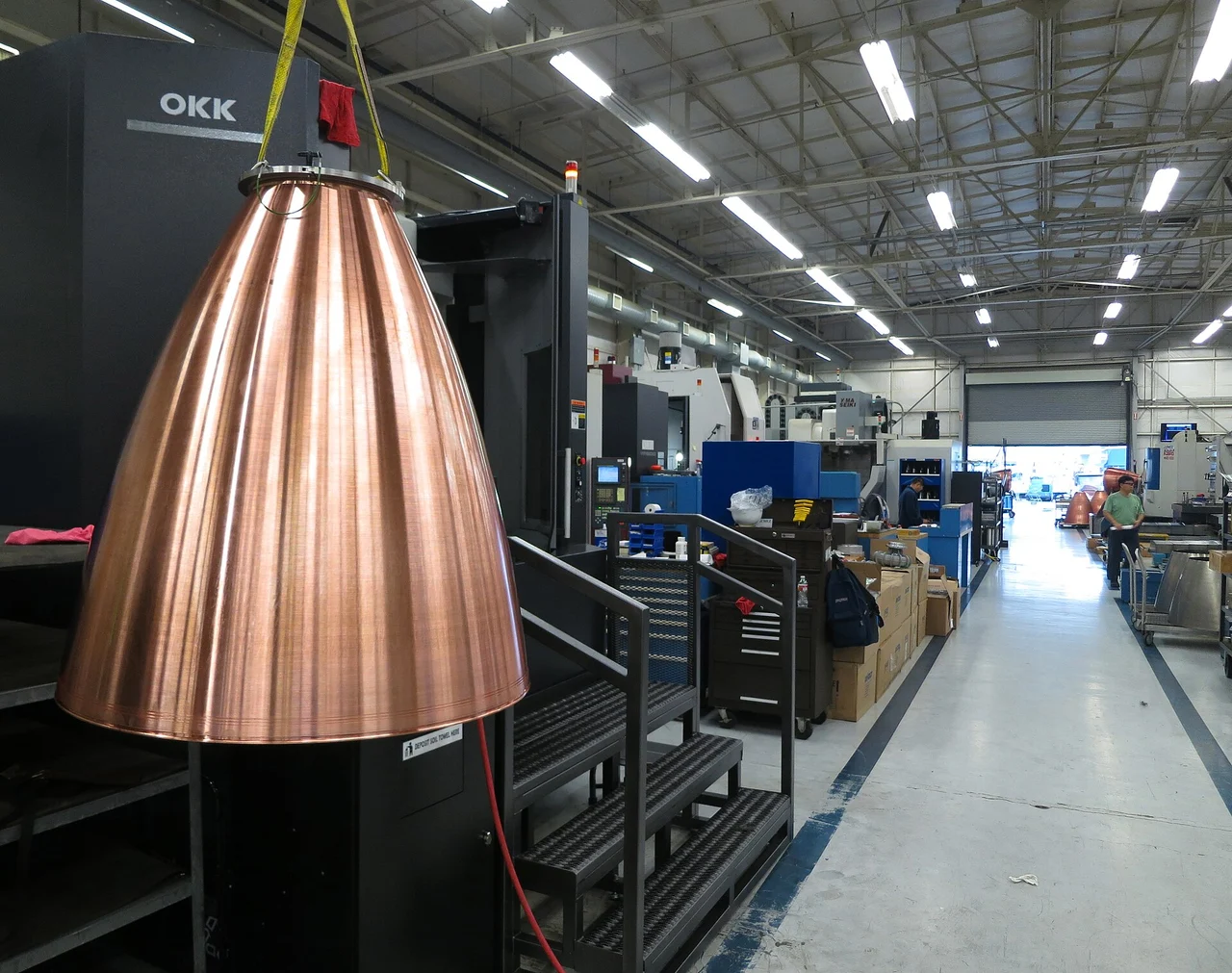 Inside the engine
Inside Merlin.
Inside the Merlin engine family: RP-1 and oxygen, the gas-generator cycle, cooling channels, vacuum nozzles and the different jobs engines do on Falcon 9.
Read the explanation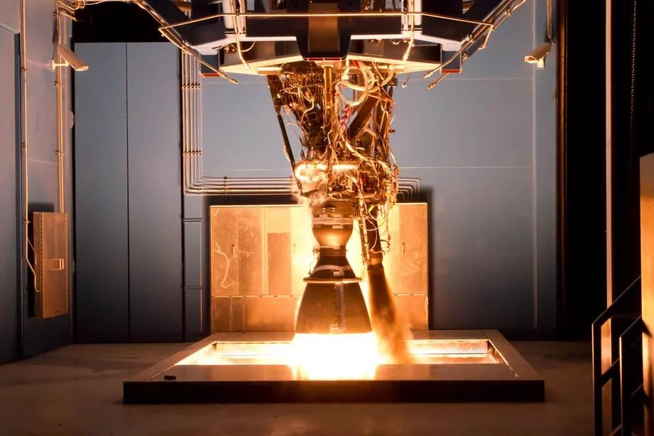 How things work
From liquid to liftoff.
Follow fuel, oxidizer and exhaust through a rocket engine, and discover why it works in empty space, how the nozzle makes thrust and what the pumps do.
Read the explanation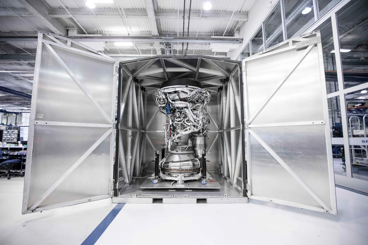 How things work
Build the bell for space.
Discover how a rocket nozzle turns hot gas into speed, why vacuum engines use large bells and how outside pressure changes the design problem near the ground.
Read the explanation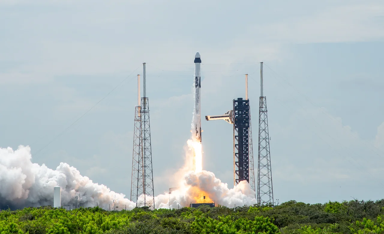 Rocket anatomy
One rocket. Two different flights.
Explore Falcon 9’s Merlin engines, two stages, payloads and booster recovery, with photographs and diagrams that explain how the flight fits together.
Read the explanation