

Inside spaceflight / 01How things work
How rocket engines work: from liquid to liftoff
Two liquids go in. A supersonic stream comes out. Between them sits a machine that must make heat, move heat and turn pressure into speed.
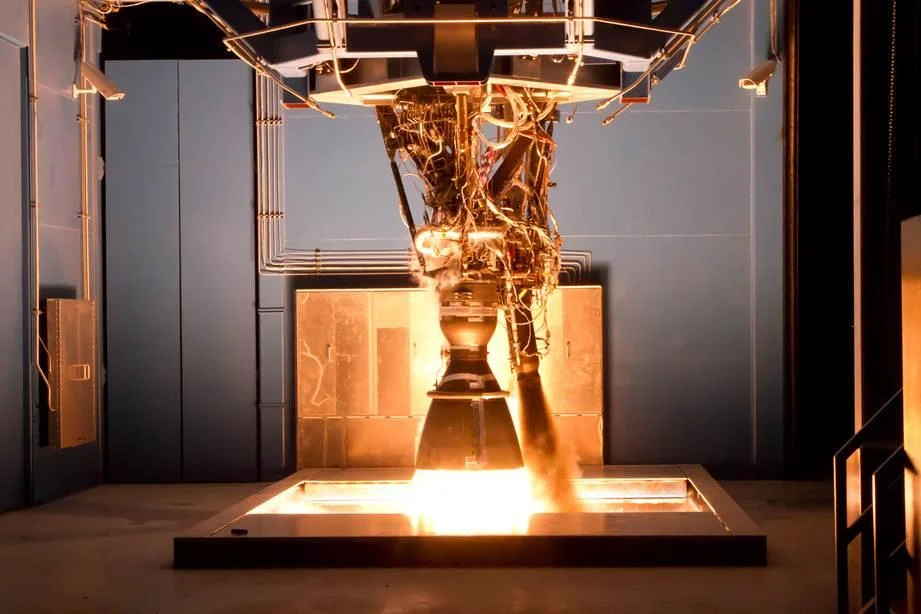
The exhaust is the other half of the story
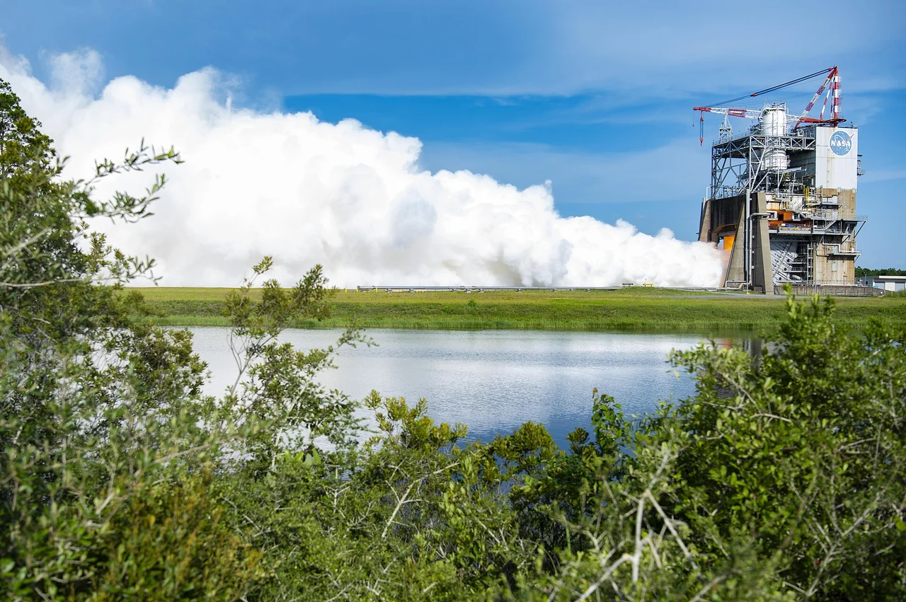
Bolt an engine to a test stand and it can shake the ground. Let that same engine operate in empty space and it can still push a vehicle forward. The partner in the exchange is the stream leaving the nozzle: propellant gains backward momentum while the rocket gains forward momentum. The exhaust can disappear into a vacuum without ever hitting a surface. [1] [2]
Imagine throwing a heavy tool while floating freely. You recoil as the tool moves away. A rocket repeats that exchange with a continuous stream of material. Combustion supplies the energy to accelerate the stream; carrying both fuel and oxidizer allows the process to continue beyond the atmosphere. [2] [3]
Where thrust comes from
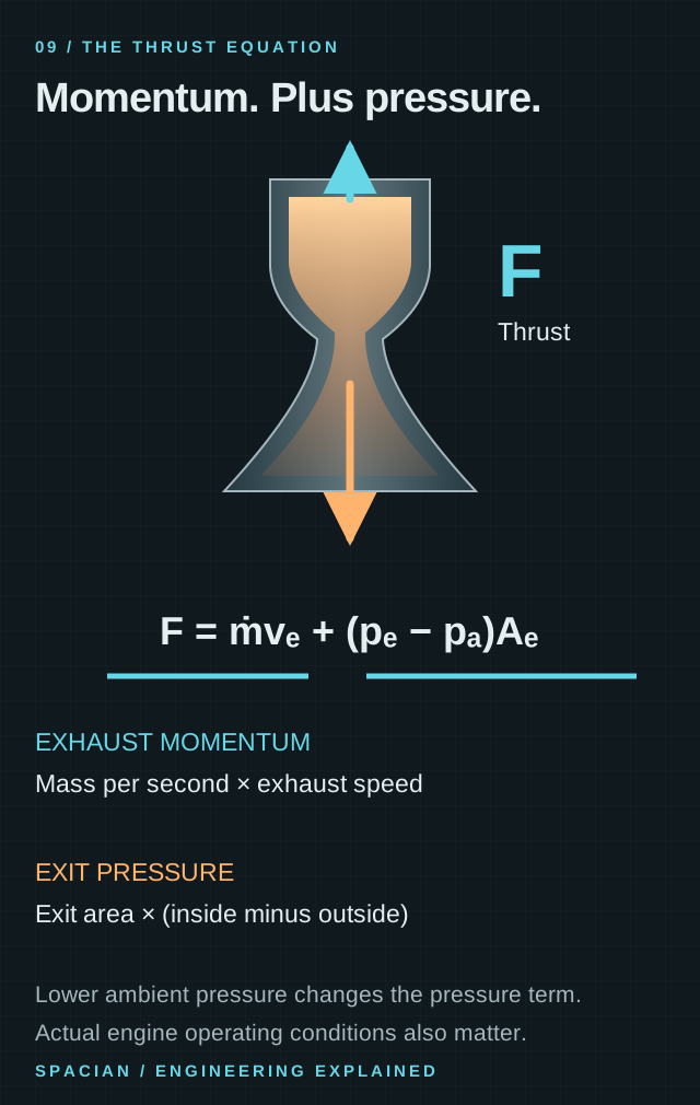
Exhaust momentum and exit pressure contribute to the force. The engine carries its own reaction mass.
- ṁ is propellant mass flow; vₑ is exhaust speed relative to the engine. Their product is a force.
- pₑ and pₐ are exit and ambient pressure; Aₑ is nozzle exit area. Their contribution can be positive or negative.
- No outside air is needed as reaction mass. The rocket carries what it expels.
Original Spacian illustration · [1] Download diagram ↗
The engine’s force has two parts. One comes from the momentum flowing out each second. The other comes from the difference between gas pressure at the nozzle exit and the pressure outside. That pressure term is why the same engine can have different sea-level and vacuum thrust ratings. [1]
Keep the liquids apart. Then mix them precisely.
A kerosene-burning jet can draw oxygen from the air. Merlin, the engine family used on Falcon, carries liquid oxygen in the rocket alongside RP-1, a highly refined kerosene. Oxygen and fuel remain separate until the engine brings them together. Together they are propellant; calling both liquids “fuel” hides one of the most important pieces of the system. [3] [4]
The injector is their meeting place. It distributes incoming liquid into the chamber so that mixing, evaporation and combustion can keep pace with the supply. The recovered F-1 injector below has a face crowded with openings. Merlin uses a pintle injector instead. Both solve the same basic problem: turn separate incoming streams into sustained combustion in a confined volume. [3] [5]
Fuel and oxidizer together are the propellants. The distinction matters: fuel releases chemical energy through reaction with the oxidizer, while both contribute mass to the exhaust. Other chemical rockets package the ingredients differently, including solid motors whose reactive ingredients are stored in a grain. [6] [3]
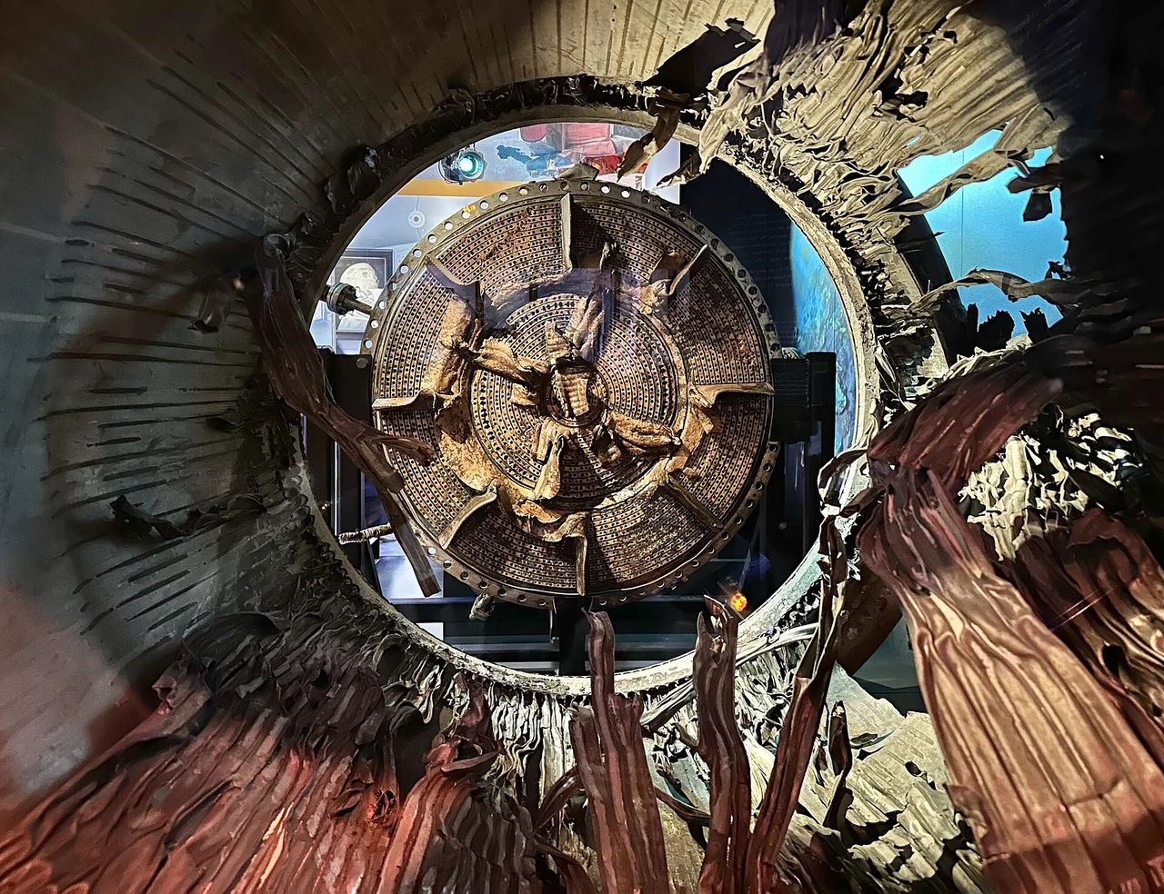
Engineering case: deliberately disturbing an F-1
During F-1 development, combustion instability could destroy chamber hardware. Sonny Morea’s team added copper baffles between injector openings to divide the injector face into compartments. A successful steady firing was only part of the evidence they needed: the engine also had to recover from a disturbance. [7]
NASA’s history describes tests that deliberately triggered a disturbance with a small explosive charge to check whether the baffles would damp the oscillations. The case gives “stable combustion” a practical meaning: the system should suppress a disruption rather than amplify it. This is F-1 history; Merlin’s pintle is a different injector design. [7]
The fire has to flow
The chamber is continually being filled and emptied. Liquid enters, combustion makes hot gas, and the nozzle carries that gas away. During steady running, the rates balance closely enough to maintain chamber pressure. A start is the difficult journey into that balance; shutdown is the controlled journey out of it. [3] [8]
The wall faces a different problem from the exhaust: the gas should leave with a great deal of energy, but the surrounding structure must remain intact. Regenerative cooling sends propellant through passages beside the hot wall, where it absorbs heat before continuing through the engine. Other designs use film cooling, ablative materials or radiation. Cooling is part of the engine’s architecture, not a finishing layer added after the combustion problem is solved. [9] [10]
Inside a liquid rocket engine
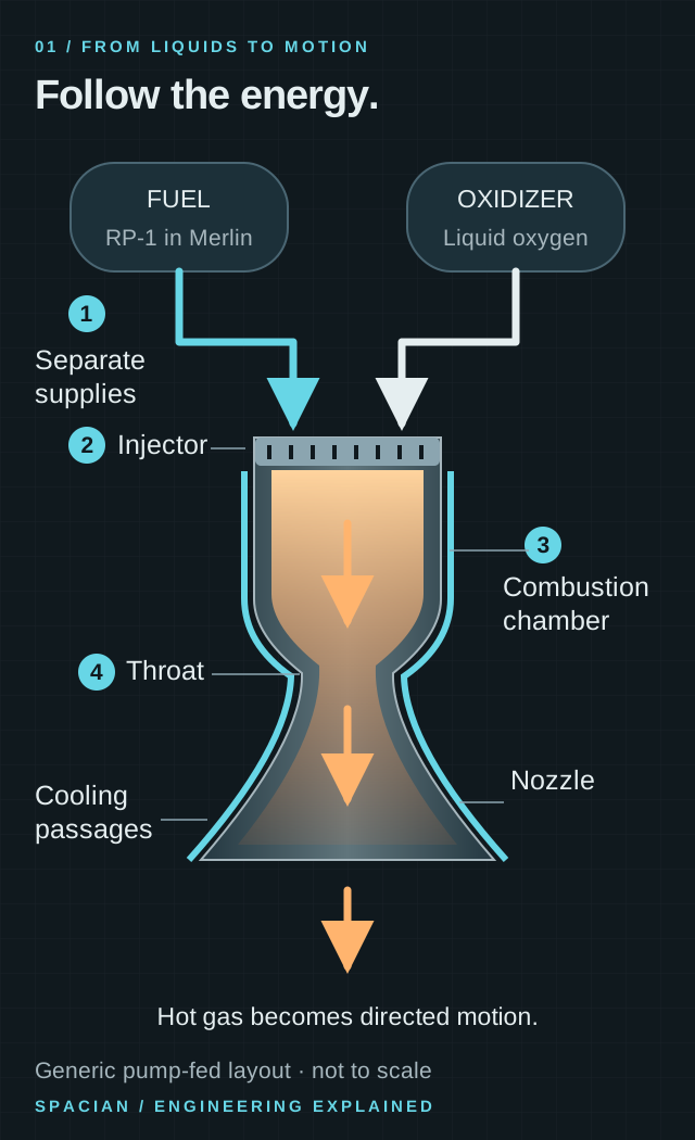
- Fuel and oxidizer arrive through separate feed paths; this drawing begins after the feed machinery.
- The injector brings the streams into the chamber. Combustion heats and pressurizes the gas.
- The throat sets the choked flow; the widening nozzle accelerates the supersonic exhaust.
Original Spacian illustration · [3] [11] [5] Download diagram ↗
Regenerative cooling makes the propellant do two jobs. Before being burned, it absorbs heat from the wall. The engine sends energy away from vulnerable metal and back into the propellant flow. In the cutaway, follow the coolant beside the wall separately from the hot gas inside it. [9] [10]
Pressure becomes speed
The nozzle first narrows to a throat, then widens into the familiar bell. In an established choked flow, gas reaches the local speed of sound at the throat. Beyond it, the supersonic stream can accelerate as the passage widens. A garden-hose intuition is unreliable here: a rocket’s exhaust is compressible, so its density changes as it expands. [11]
The widening section converts some of the gas’s thermal energy into directed speed, while its static pressure falls. The nozzle is not simply a funnel that points a flame. Its expansion determines both the speed and pressure of the gas leaving the engine, and those quantities appear in the thrust equation. [11] [1]
This gives the nozzle designer two linked targets: a fast exhaust and a useful exit pressure for the surroundings. Near the ground, outside air presses back on the emerging flow. In space, a larger expansion can extract more directed speed before the gas leaves the hardware. The nozzle guide lets you change those conditions yourself. [12] [13]
From chamber pressure to exhaust speed
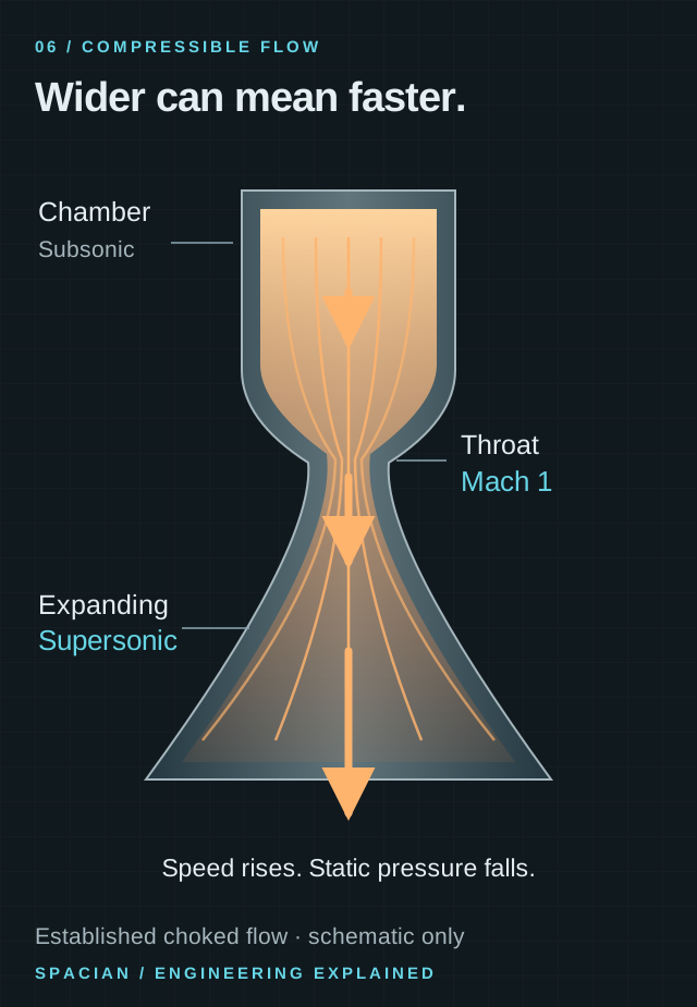
- The throat is the smallest flow area. In an established choked flow, the gas reaches local Mach 1 there.
- A widening passage accelerates the supersonic stream while its static pressure falls.
- Arrow lengths and streamline spacing are qualitative, not a flow simulation.
Original Spacian illustration · [11] [1] Download diagram ↗
The pumps have to beat chamber pressure
Putting a tank above the engine does not solve the feed problem. Liquid has to enter a chamber that is already pushing back at high pressure, and it must arrive at the required rate. A pressure-fed system obtains the necessary pressure from its tanks. A pump-fed system raises pressure on the way to the engine, shifting some of the design burden from the tank to machinery. [14] [3]
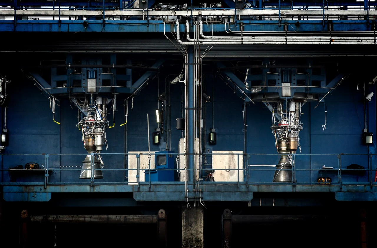
The pumps need power of their own. Merlin burns a smaller propellant flow in a gas generator, expands that gas through a turbine and uses the turbine’s shaft to drive the oxygen and fuel pumps. The main chamber and the pump-power system are linked but do different work. Following those two paths explains much of the plumbing above the bell. [5]
The feed pressure must also cover losses in lines, valves, cooling passages and the injector. Raising chamber pressure therefore creates a chain of demands upstream. More pressure in the main fire means more work for the machinery feeding it, which in turn needs a source of power. That is the reason for the smaller fire in a gas-generator engine. [15] [14]
Force now, speed over the whole burn
Consider a deliberately simple example: an engine expels 100 kilograms of propellant each second at 3,000 metres per second relative to the vehicle. The momentum contribution is 100 × 3,000 = 300,000 newtons, or 300 kilonewtons. We have left the nozzle’s exit-pressure correction aside. Doubling the mass flow at the same exhaust speed doubles this contribution; a brighter-looking flame is not an independent input to the equation. [1]
Specific impulse asks a different question: how much thrust does the engine obtain per unit propellant weight flow? For the momentum-only example, dividing the effective exhaust speed by standard gravity gives about 306 seconds. Those seconds are a performance unit, not a claim that the engine runs for 306 seconds. Thrust describes force; specific impulse describes propellant economy under stated operating conditions. [16]
As propellant leaves, the vehicle becomes lighter. With the same thrust and no other forces, its acceleration rises. Over a complete burn, the ideal rocket equation connects exhaust performance with the ratio of starting mass to finishing mass. That is where an engine explanation becomes a vehicle explanation: carrying the propellant helps produce motion, but also gives the engine more mass to move. [17]
A worked example, not an engine specification
- Exhaust momentum contribution
- 100 kg/s × 3,000 m/s300 kN
- Momentum-only specific impulse
- 3,000 m/s ÷ 9.80665 m/s²≈ 306 s
Go deeper: why doubling propellant does not double speed
For a constant effective exhaust speed vₑ, the ideal velocity change is Δv = vₑ ln(m₀/mf). At an illustrative 3,000 m/s and a starting-to-finishing mass ratio of 2, the result is about 2,079 m/s. At a ratio of 4 it is about 4,159 m/s. Here mf includes every kilogram still carried after the burn. [17]
These are ideal changes in velocity for a hypothetical vehicle, with gravity and aerodynamic losses omitted. The logarithm captures a central difficulty: additional propellant must itself be accelerated before it can be expelled. Staging helps by discarding hardware that has finished its job. [17]
Read the evidence
Sources & image credits
- NASA Glenn · Rocket thrust equation ↗
- NASA · Basics of Space Flight: Gravity and mechanics ↗
- NASA Glenn · Liquid rocket engine ↗
- SpaceX · Falcon 9 and Merlin ↗
- SpaceX · Falcon User’s Guide, May 2025 ↗
- NASA · Basics of Space Flight: Launch ↗
- NASA · Solving combustion instability in the F-1, 2019 ↗
- NASA · Saturn V, starting the F-1 engine, Appendix B ↗
- NASA Technology Transfer · Coolant channels in rocket chambers and nozzles ↗
- NASA Glenn · Historical nozzle-cooling research ↗
- NASA Glenn · Nozzle design ↗
- NASA Glenn · Isentropic flow equations and area–Mach relation ↗
- NASA Glenn · Rocket thrust equations ↗
- NASA NTRS / AIAA · Liquid propulsion systems, engine power cycles ↗
- NASA SP-8107 · Turbopump Systems for Liquid Rocket Engines, 1974 ↗
- NASA Glenn · Specific impulse ↗
- NASA Glenn · Ideal rocket equation ↗
Technical explanation by Spacian, reviewed against the linked sources. Photographs retain their original dates, creators and reuse terms in their captions. Original diagrams explain mechanisms and do not reproduce engineering drawings or flight telemetry. Editorial policy and corrections.
Continue the story
Follow the mechanism
 Engine mechanisms
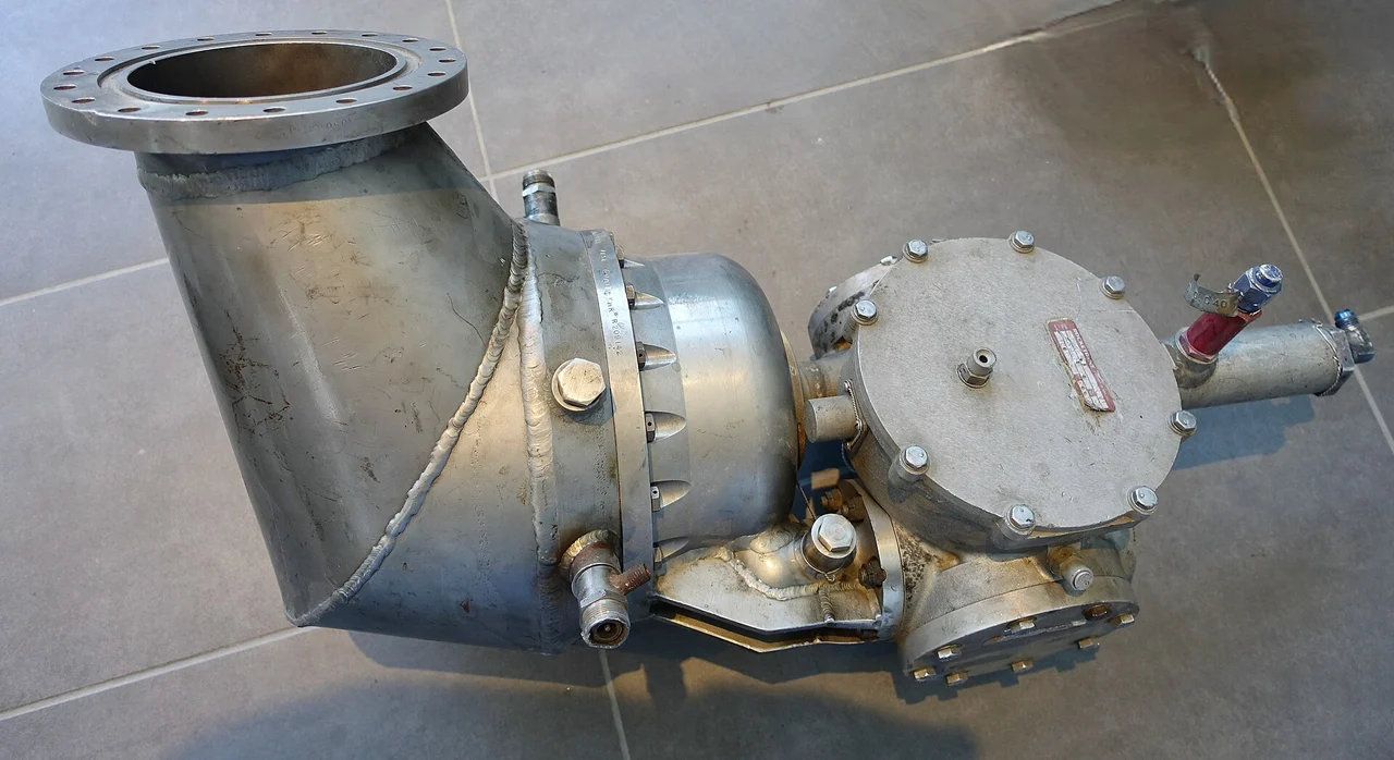
The engine inside the engine.
Trace fuel, oxidizer, turbine and pumps through a gas-generator rocket engine, and understand the open-cycle tradeoff behind engines such as Merlin and F-1.
Read the explanation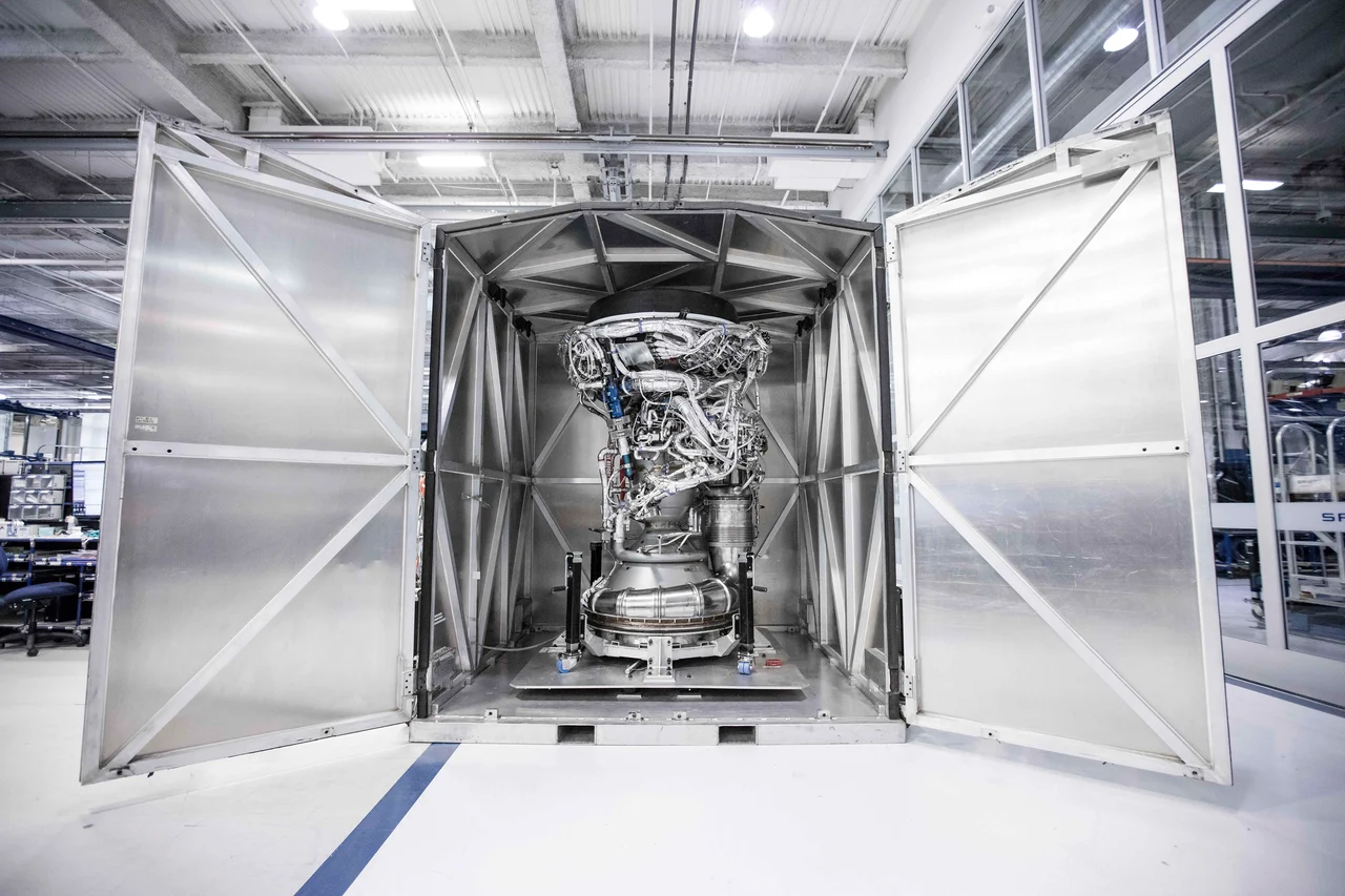 How things work
Build the bell for space.
Discover how a rocket nozzle turns hot gas into speed, why vacuum engines use large bells and how outside pressure changes the design problem near the ground.
Read the explanation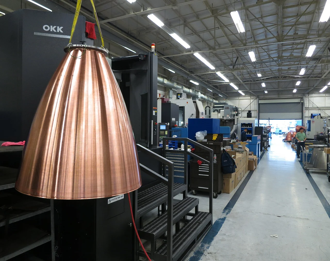 Inside the engine
Inside Merlin.
Inside the Merlin engine family: RP-1 and oxygen, the gas-generator cycle, cooling channels, vacuum nozzles and the different jobs engines do on Falcon 9.
Read the explanation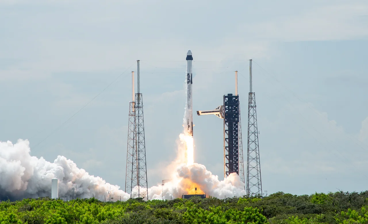 Rocket anatomy
One rocket. Two different flights.
Explore Falcon 9’s Merlin engines, two stages, payloads and booster recovery, with photographs and diagrams that explain how the flight fits together.
Read the explanation