

Inside spaceflight / 04How things work
Rocket nozzles: why bigger works better in space
Merlin Vacuum wears an enormous bell. A first-stage engine cannot simply copy it. The reason is a pressure problem you can explore with a working ideal-flow model.
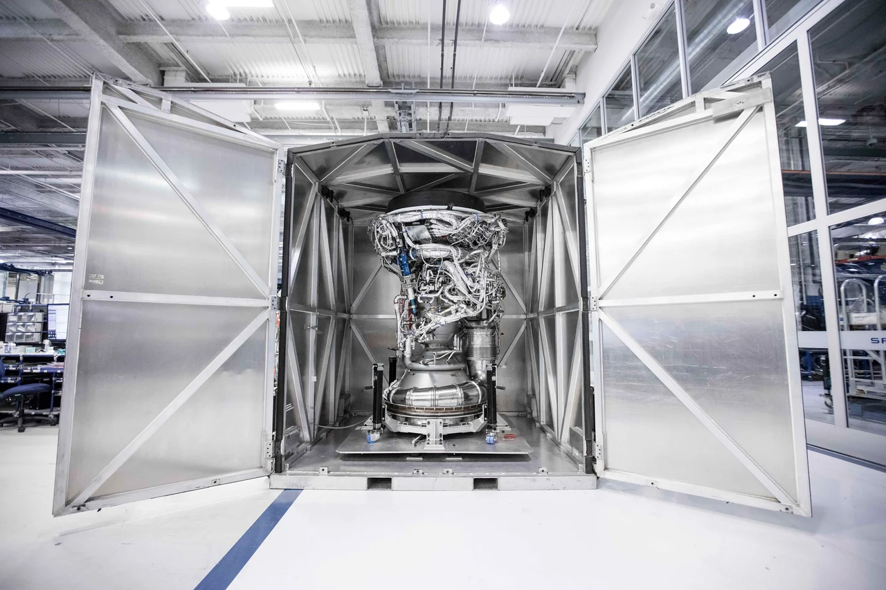
One engine has to fit the pressure outside
The Merlin Vacuum in the opening photograph has a bell designed for low ambient pressure. A nozzle like this gives the exhaust more room to expand before it leaves the engine. At sea level, the same expansion can take the exit pressure below the pressure of the air outside. The useful size of a bell depends on where the engine works. [1] [2]
Inside a converging-diverging nozzle, the flow passes through a narrow throat and into a widening passage. In established choked operation, it reaches local Mach 1 at the throat. Downstream, the supersonic gas accelerates while its density, static pressure and temperature fall. The larger passage is converting thermal energy into directed motion. [2] [3]
The throat and exit therefore have different jobs. With chamber conditions fixed, throat area sets the choked mass flow. Exit-to-throat area ratio controls the expansion of that flow. You can change the second quantity in the experiment without silently changing the first. [4]
Where the exhaust speeds up
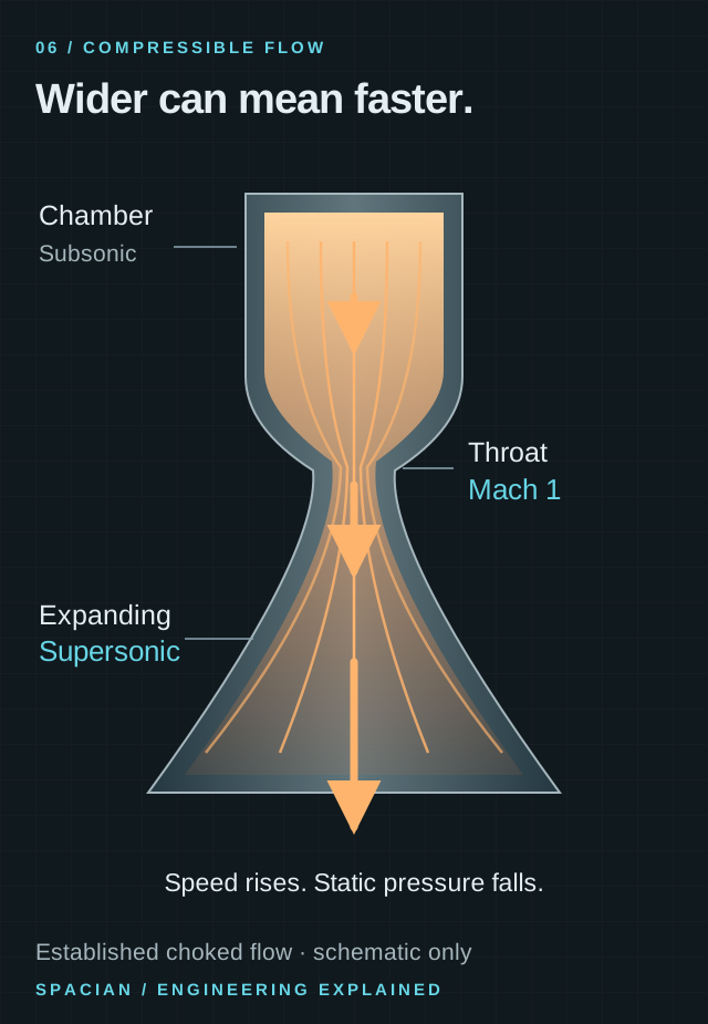
Conceptual converging-diverging nozzle, not to scale. The labels describe an established choked flow; the illustration is not a simulation of a specific engine.
- The throat is the smallest flow area. In an established choked flow, the gas reaches local Mach 1 there.
- A widening passage accelerates the supersonic stream while its static pressure falls.
- Arrow lengths and streamline spacing are qualitative, not a flow simulation.
Original Spacian illustration · [2] [5] Download diagram ↗
Go deeper: how a widening passage accelerates a supersonic flow
Continuity requires ṁ = ρAv: density × area × speed stays constant along the ideal steady flow. Because density changes, widening the passage does not require speed to fall. Combining continuity with the momentum relation gives dA/A = (M² − 1) dv/v. For supersonic flow, M > 1, so increasing area goes with increasing velocity. [3] [2]
The throat is the transition at M = 1. Reaching the intended supersonic branch also depends on pressure conditions; a converging-diverging shape alone does not guarantee that state at every operating point. [2]
Change the bell. Then change the world around it.
Start at an area ratio of 40:1 with sea-level pressure selected. Without changing the nozzle, select vacuum. The hypothetical model’s thrust rises from about 145.8 kN to 186.4 kN. It has gained 40.5 kN while passing the same mass flow through the same hardware. [4] [3]
Now keep vacuum selected and increase the area ratio: more expansion continues improving ideal thrust across the displayed range. Return to sea level and do the same thing. The curve reaches a maximum and then falls. A larger exit has changed both exhaust speed and exit pressure, and the outside pressure can make the trade unfavorable. [4] [3]
Experiment with the mechanism
Build the bell for its surroundings.
Keep the chamber and throat fixed. Change expansion and outside pressure.
At 10.0:1 and 101.3 kPa outside, this ideal model gives 162.9 kN. Exit pressure is above ambient.
Try this: set 40:1 at sea level, then select vacuum. Keep the same nozzle and watch the pressure contribution change.
Hypothetical engine: steady one-dimensional isentropic flow, chamber pressure 10 MPa, temperature 3,500 K, throat area 0.01 m², γ = 1.22 and gas constant 355 J/(kg·K). These are teaching assumptions, not Merlin specifications. Shocks, separation, heat transfer, losses and structural limits are omitted. The drawn contour is schematic.
How the calculation works
We solve the supersonic area–Mach relation, derive exit pressure and temperature from the isentropic relations, then calculate mass flow, exhaust velocity and F = ṁvₑ + (pₑ − pₐ)Aₑ. At the default settings, ṁ is about 58.5 kg/s. The curve evaluates the same equations across area ratios 2–80.
The experiment assumes a fixed hypothetical chamber and steady, one-dimensional isentropic flow. It keeps the gas properties constant and the flow attached. Real nozzles also face shocks, separation, heat transfer and structural limits. The model isolates expansion and pressure so you can see their effect before adding those complications. [3] [6]
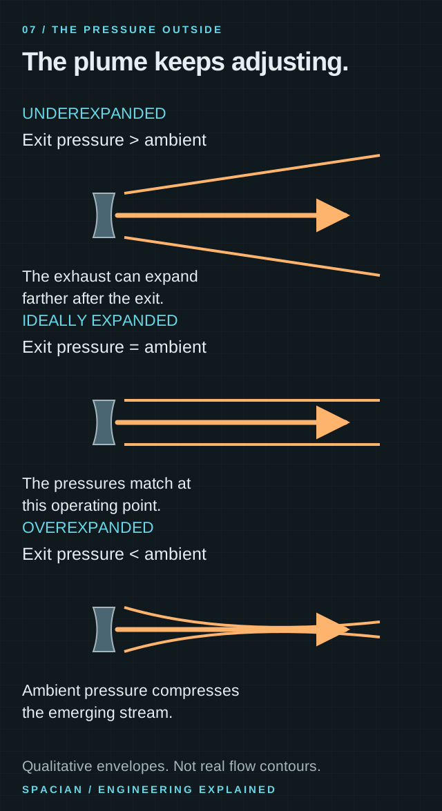
The three pressure relationships
When gas leaves at a pressure above ambient, the stream is underexpanded: further expansion can happen after it exits. When the exit and ambient pressures match, the flow is ideally expanded at that operating point. When exit pressure is below ambient, the flow is overexpanded relative to its surroundings. The names describe a pressure relationship, not three different fuels or nozzle materials. [2] [5]
Overexpansion is especially important near the ground and during transients. Under some conditions, flow can separate inside the nozzle, creating asymmetric loads. A smooth ideal-flow calculation does not predict those events. The real operating envelope has to account for them, which is why a vacuum nozzle cannot simply be judged by its potential expansion in empty space. [6]
The selected label in the experiment follows the same rule as these drawings: compare exit pressure with ambient pressure. At a fixed nozzle ratio, lowering ambient pressure can move the model from overexpanded, through a near match, to underexpanded. No hardware change is required for that progression. [5]
The same question at three exit pressures
Compare exit pressure with the surroundings. The envelopes show qualitative adjustments.
Qualitative pressure comparison, not measured plume shapes or a performance prediction. Actual exhaust structure depends on the engine and its operating conditions.
- Underexpanded: the exit pressure remains above the surroundings, so the stream expands after leaving.
- Ideally expanded: exit and ambient pressure match at that operating point.
- Overexpanded: outside pressure is higher. Strong overexpansion may separate flow inside the nozzle; that complex flow is not drawn here.
Original Spacian illustration · [2] [5] [6] Download diagram ↗
Merlin puts the difference into real hardware
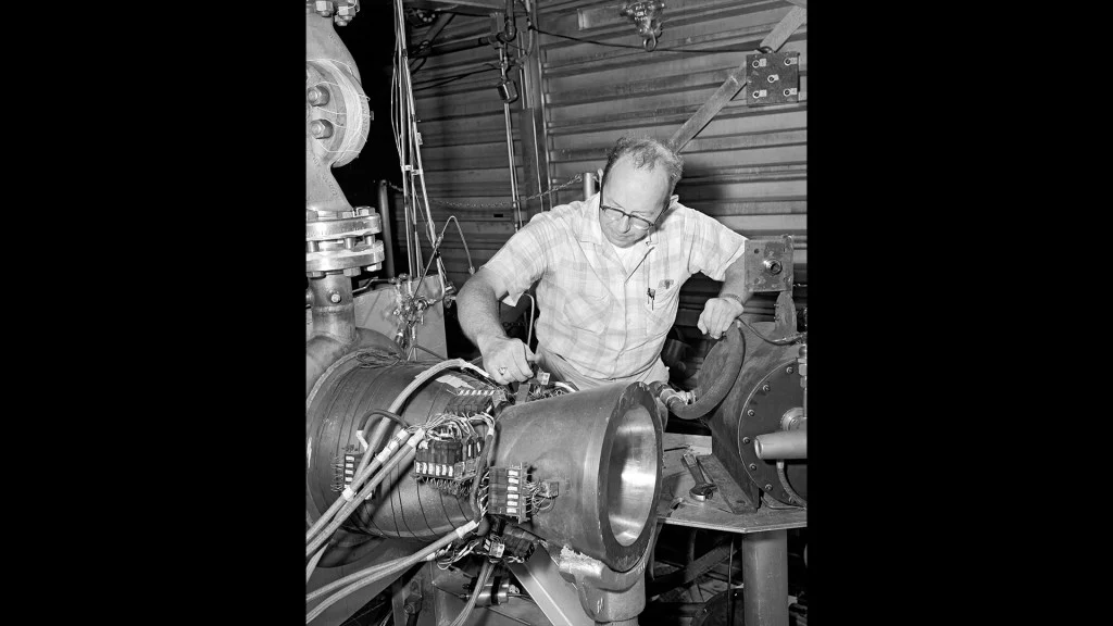
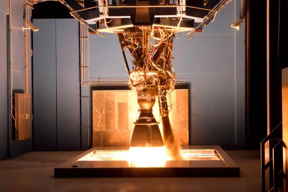
Falcon 9’s first-stage engines operate during liftoff, when substantial atmosphere surrounds the vehicle. Its upper-stage Merlin Vacuum works after stage separation in much lower ambient pressure. The large expansion nozzle in the opening photograph belongs to that upper-stage role. The compact sea-level nozzle in the test photograph below has a different operating environment. [1] [7]
SpaceX’s May 2025 guide gives the fixed MVac nozzle an expansion ratio of 165:1. A large ratio is useful in low pressure because the gas can expand farther. The actual design still has to fit in the vehicle, carry its own mass and survive its thermal and structural environment. A model that calculates only expansion cannot settle those other constraints. [1] [2]
That design choice also has a packaging cost. The bell must fit the upper-stage arrangement and carry its own mass, and its wall must survive the flow passing through it. An area ratio describes expansion geometry; it is one input to an engine design rather than a complete performance score. [1] [2]
Account for the extra 40.5 kilonewtons
The thrust equation is F = ṁvₑ + (pₑ − pₐ)Aₑ. For unchanged attached exit flow, the momentum term ṁvₑ stays fixed when only ambient pressure changes. The increase comes from subtracting a smaller ambient pressure over the same exit area. [5]
In the experiment, the throat is 0.01 m². At an area ratio of 40, the exit is 0.4 m². Lowering ambient pressure from 101.3 kPa to zero changes thrust by 101.3 kPa × 0.4 m² = 40.52 kN. The result exactly explains the difference between the two calculated readouts; it does not require the exhaust velocity to increase. [4]
Changing the bell is different from changing ambient pressure. The area–Mach relation determines a new exit Mach number, and the isentropic relations give a new exit pressure and velocity. The model then puts all three changes—area, pressure and speed—back into the thrust equation. [3] [4]
The specification becomes something you can see
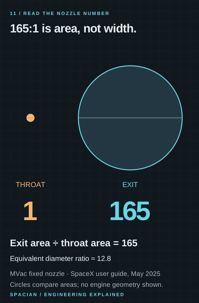
A circle’s area grows with the square of its diameter. An exit-to-throat area ratio of 165 therefore corresponds to a diameter ratio of the square root of 165, about 12.8, for circular sections. The circles below preserve that area relationship. They do not reproduce the complete contour or dimensions of an MVac engine. [1]
The comparison below gives the specification a visible meaning: the circles preserve the 165:1 area relationship while their diameters differ by about 12.8. The complete engine contour has its own length and curvature, which these circles do not encode. [1]
165 to one is an area ratio
- Expansion ratio compares nozzle exit area Aₑ with throat area Aₜ. It does not compare their diameters.
- For circular sections, a 165:1 area ratio means a diameter ratio of √165, approximately 12.8.
- SpaceX’s May 2025 guide lists 165:1 for its fixed MVac nozzle. This is a dated documented configuration, not a measurement of every photograph.
Original Spacian illustration · [1] Download diagram ↗
Return to the photograph with three questions in mind. How much expansion does the nozzle provide? What pressure will surround it? What thermal and structural work does its wall have to do? The large bell becomes the visible answer to a particular set of operating conditions. [2] [5]
Read the evidence
Sources & image credits
- SpaceX · Falcon User’s Guide, May 2025 ↗
- NASA Glenn · Nozzle design ↗
- NASA Glenn · Isentropic flow equations and area–Mach relation ↗
- NASA Glenn · Rocket thrust equations ↗
- NASA Glenn · Rocket thrust equation ↗
- NASA NTRS · Flow-separation side loads in rocket nozzles ↗
- SpaceX · Falcon 9 and Merlin ↗
Technical explanation by Spacian, reviewed against the linked sources. Photographs retain their original dates, creators and reuse terms in their captions. Original diagrams explain mechanisms and do not reproduce engineering drawings or flight telemetry. Editorial policy and corrections.
Continue the story
Follow the mechanism
 Inside the engine
Inside Merlin.
Inside the Merlin engine family: RP-1 and oxygen, the gas-generator cycle, cooling channels, vacuum nozzles and the different jobs engines do on Falcon 9.
Read the explanationHow things workFrom liquid to liftoff.
Follow fuel, oxidizer and exhaust through a rocket engine, and discover why it works in empty space, how the nozzle makes thrust and what the pumps do.
Read the explanation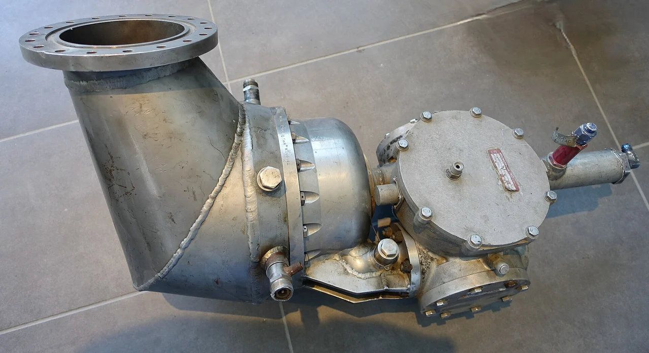 Engine mechanisms
The engine inside the engine.
Trace fuel, oxidizer, turbine and pumps through a gas-generator rocket engine, and understand the open-cycle tradeoff behind engines such as Merlin and F-1.
Read the explanation Rocket anatomy
One rocket. Two different flights.
Explore Falcon 9’s Merlin engines, two stages, payloads and booster recovery, with photographs and diagrams that explain how the flight fits together.
Read the explanation